Operation2722−1/A1
Winterthur Gas & Diesel Ltd.
2/ 2
2. Function
Fuel flows through the high pressure (HP) fuel pipes (9, Fig. 1) to the three injection
valves (1).
The control valve for the injection valves is activated, which moves the needle to the
open position. Fuel flows through the holes in the nozzle tip (3, Fig. 2) and into the
combustion chamber as a spray. A small quantity of fuel flows through the control fuel
return.
3. Cooling
Oil from the lubricating oil system lubricates the injection valves and keeps them cool
(see 8016−1 Lubricating Oil System). When the engine has stopped, the lubrication
also stops. This is because the temperature of the remaining fuel in the injectors
would decrease too much.
Oil flows through the lube oil inlet (4) through bores in the injection valve. The oil flows
back through the bores in the injection valve through the lube oil return (4, Fig. 1).
I
I
FS
1
2
3
9
WCH01214
4
5
6
7
8
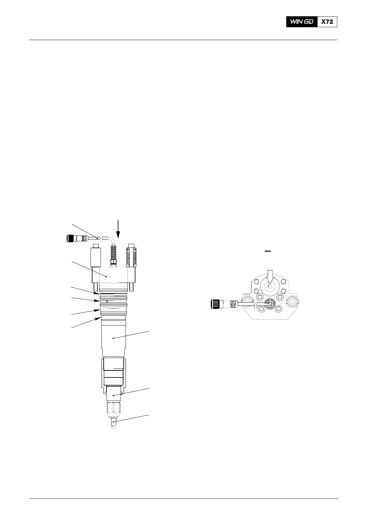
Fig. 2: Injection Valve
1 Injection valve 6 Annular groove − fuel / lube oil leakage
2 Nozzle body 7 Annular groove −control fuel return
3 Nozzle tip 8 Valve bush
4 Annular groove − lube oil inlet 9 Electrical cable to control valve
5 Annular groove − lube oil return FS Fuel supply
2014
Injection Valve (FAST Nozzle)