Operation3603−1/A1
Winterthur Gas & Diesel Ltd.
2/ 2
Key to Fig. 1: Articulated Lever − Location
1 Column 9 Top end bearing shell
2 Support 10 Connecting rod
3 Oil inlet (crosshead lubrication) 11 Guide shoe
4 Bottom lever 12 Piston rod
5 Top lever OB Oil bore (crosshead lubricating oil to
6 Connection piece bottom end bearing)
7 Bore (crosshead lubricating oil) OI Oil inlet
8 Crosshead pin RS Ring space (crosshead lubricating oil)
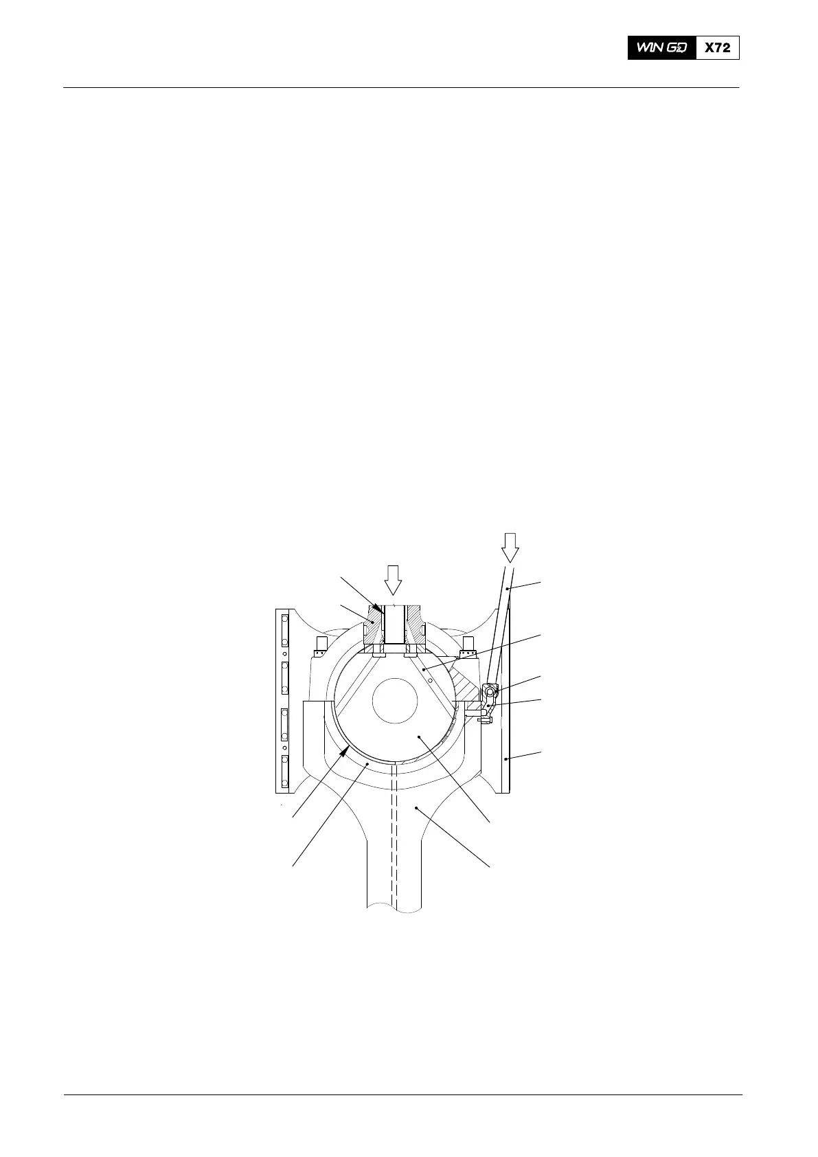
3. Piston Cooling
Bearing oil flows from the oil inlet (OI, see Fig. 1 and Fig. 2) through the support (2),
the bottom lever (4) and the top lever (5) to the connection piece (6). The oil flows
through the bore (7) into the ring space in the crosshead pin (8), through bores in the
top end bearing shell (9). The oil flows through the outer part of the oil pipe (13)
through the piston rod (12) to the piston.
The oil then flows down through the inner part of the oil pipe (13) through the oil
return (OR) to the center bore in the crosshead pin (8). Some of the piston cooling oil
is used to lubricate the guide shoes (11) and the guide shoe pins. The remaining oil
flows into the crankcase.
For more data, see 3326−1 Crosshead and Guide Shoe.
WCH02223
PC
OR
5
14
6
16
11
8
10
15
9
12
13
Fig. 2: Cross-section through Crosshead
5 Top lever 13 Oil pipe
6 Connection piece 14 Bore (in the crosshead pin)
8 Crosshead pin 15 Ring space (piston cooling oil)
9 Top end bearing shell 16 Bore (piston cooling oil)
10 Connecting rod
11 Guide shoe PC Piston cooling (oil inlet)
12 Piston rod OR Oil return
Crosshead Lubrication and Piston Cooling
2014