Operation
5556−1/A1
Winterthur Gas & Diesel Ltd.
3/ 3
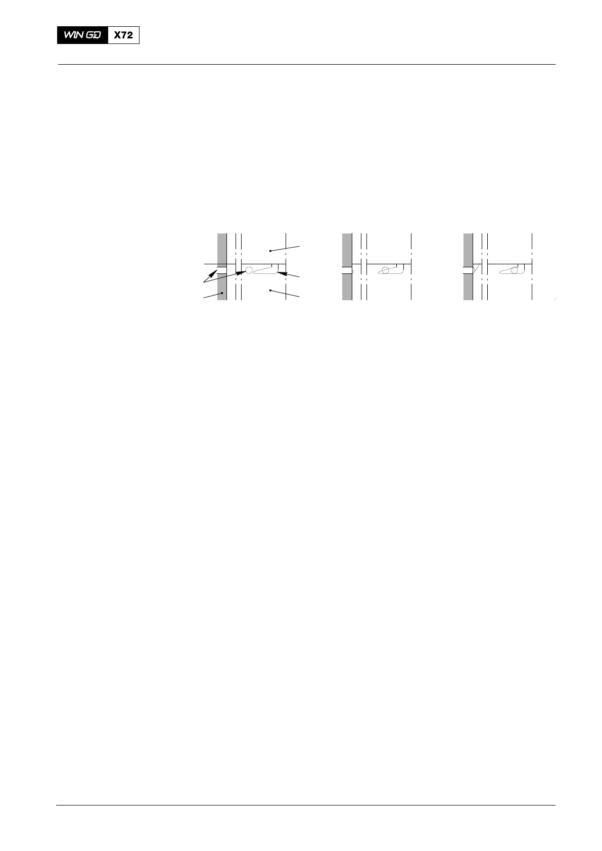
When the pump plunger passes BDC, fuel flows through the two inlet bores (5, Fig. 3)
and the two control grooves (2) into the plunger chamber (1). The quantity of fuel that
enters the plunger chamber (1) is related to the control position (between 0 for zero
supply and 10 for maximum supply).
Note: No fuel is supplied in the position 0 (zero).
POSITION 5POSITION 0 POSITION 8
BDC
1
3
4
5
2
008.645/00
008.645/00008.645/00
Fig. 3: Control Grooves of Pump Plunger
1 Plunger chamber 4 Pump cylinder
2 Control groove 5 Inlet bore
3 Pump plunger
2014
Fuel Pump