Operation
6735−1/A1
Winterthur Gas & Diesel Ltd.
3/ 4
2.1 Open and Close Phases
When the outside air temperature decreases below the values given in Table 1, the
solenoid valve (19, Fig. 2) energizes. The scavenge air pressure flows through the
pressure control valve (1), then through the non-return valve (3) to the pressure
space (13). The pressure in the pressure space (13) decreases.
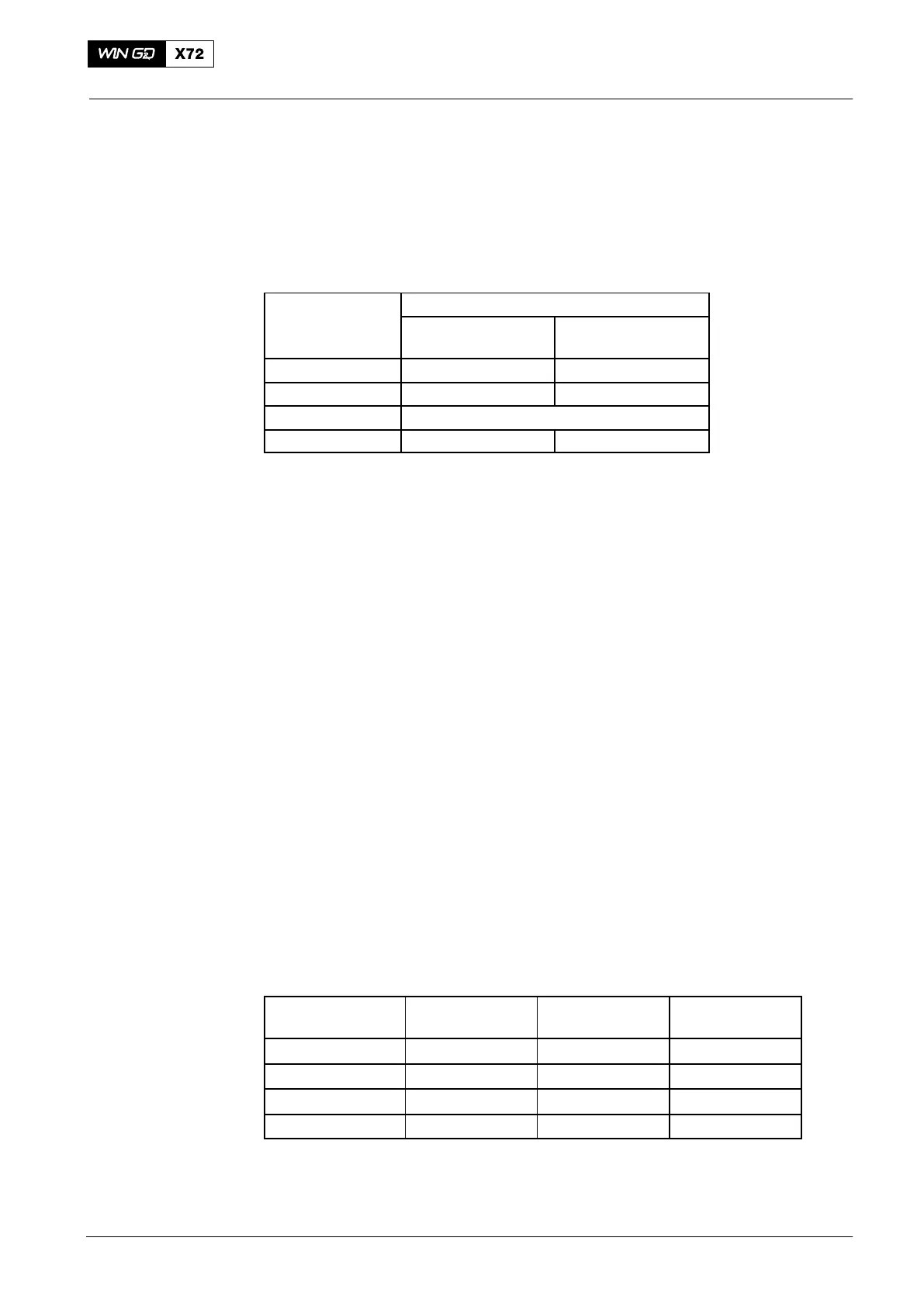
Table 1: Temperatures and Pressures
Waste Gate
Valve Movement
External Temperatures
Engine without
WHR
Engine with
WHR
Opens at
+5° C −5° C
Opens at
+10° C 0° C
Pressures
Opens at 0.75 bar 0.7 bar
Note: WHR (Waste Heat Recovery System)
The decreased pressure in the pressure space (13) is now less than the pressure in
the pressure area (5). The pressure in the pressure area (5) moves the piston (6)
against the force of the compression spring (7) and the waste gate valve opens.
Scavenge air then flows through the silencer into the engine room.
The temperature sensor (20) (TE3991C) measures the outside air temperature to
energize/ de-energize the solenoid valve (19).
When the solenoid valve energizes, the waste gate valve opens.
When the solenoid valve de-energizes, the waste gate valve closes.
3. Adjustments
3.1 Valve Stroke Check
This task is only necessary after faults, overhauls or when the waste gate valve was
replaced.
Do this check when the engine has stopped, or when the engine operates at a load of
75% or less at the usual suction temperatures (more than +5_C).
1) Remove and discard the lockwire from the adjustment screw (9).
2) Loosen the locknut (10).
3) Turn the adjustment screw (9) fully clockwise to its limit.
4) Adjust the nominal piston stroke with reference to Table 1 (one full turn of the
adjustment screw (9) is equal to a piston movement of 1.5 mm).
Table 2: Valve Stroke
Number of
Cylinders
Number of
Waste Gates
Piston Stroke
(mm)
Number of
Turns
5 1 6.0 4
6 1 6.75 4.5
7 1 8.25 5.5
8 1 9.0 6.0
5) Tighten the locknut (10).
6) Lock the adjustment screw (9) in position with lockwire.
2015−03
3
Scavenge Air Waste Gate