Operation7218−1/A1
Winterthur Gas & Diesel Ltd.
2/ 12
2. Lubricating Oil System − Overview
The diagram Fig. 1 shows the complete system, which has the components that
follow:
D Cylinder lube oil tank (1) for cylinder lubricating oil (plant side)
D Duplex filter (10) with a lever to change filters
D Lubricating quills (2) with a non-return valve and an injection nozzle
D System control from the ECS (see 4002-1, paragraph 3.4 Cylinder Lubricating
Control).
The cylinder lubricating pumps 25-7230_C#_1 (one for each cylinder) have the parts
that follow:
D Cylinder control module 20 (CCM-20)
D 4/2-way solenoid valve (2)
D Pressure transmitter (3).
WCH02267
3
RAIL UNIT
8
10
1
4
6
2
5
7
9
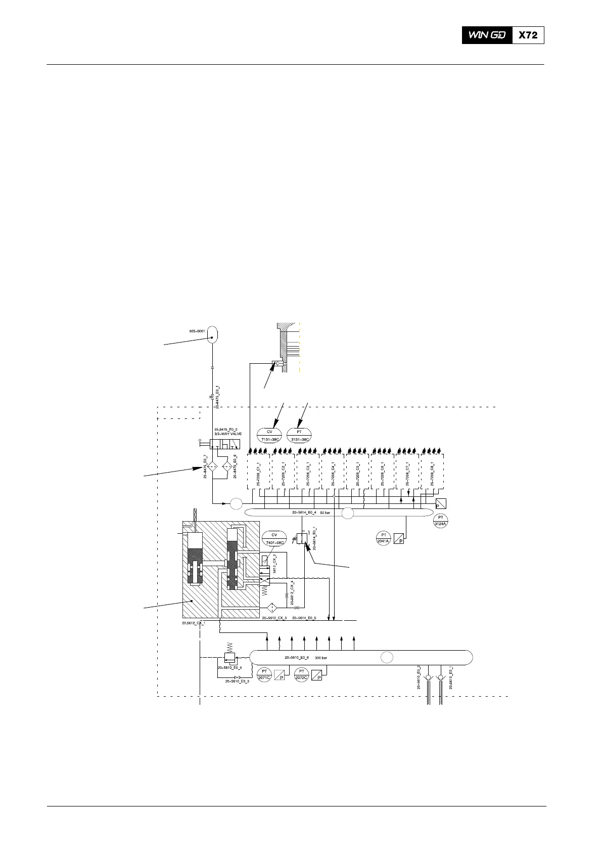
Fig. 1: Schematic Diagram − Cylinder Lubrication System
1 Cylinder lube oil tank 6 Pressure reducing valve
2 Lubricating quills 7 Servo oil rail
3 Control valve CV7131C − CV7138C 8 Exhaust valve control unit
4 Pressure transmitter PT3131C − PT3138C 9 Lubricating oil supply pipe
5 Servo oil supply pipe 10 Duplex filter
2015-03
Cylinder Lubrication