Operation
8017−1/A1
Winterthur Gas & Diesel Ltd.
3/ 3
PLANTENGINE
1
2
14
3
6
WO
WI
5
7
8
4
9
10
11
12
13
15
17
18
19
20
21
WO − Cylinder Cooling16
CYL. 1 CYL. #
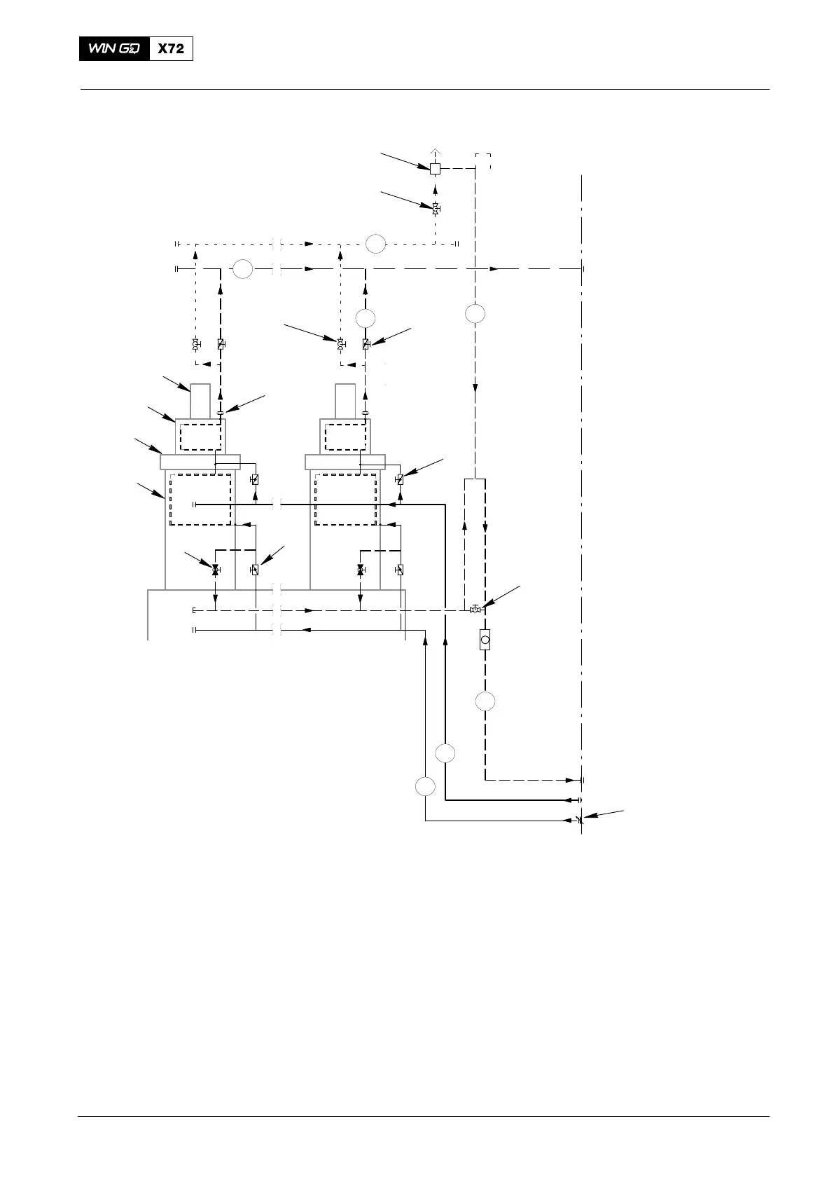
Fig. 1: Lubricating Oil System
1 Vent unit 13 Throttle (cylinder outlet)
2 Ball valve 14 Ball valve
3 Butterfly valve (cylinder outlet) 15 Cylinder outlet
4 Butterfly valve (cylinder inlet) 16 Outlet pipe (cylinder cooling water)
5 Ball valve (to drain the system) 17 Outlet pipe (cooling water)
6 Adjustable throttle (water inlet) 18 Supply pipe
7 Butterfly valve (cylinder liner inlet) 19 Inlet pipe (to cylinder liner inlet)
8 Ball valve (to drain the cylinder) 20 Vent pipe
9 Cylinder liner 21 Drain pipe
10 Water guide jacket
11 Cylinder cover WI Cooling water inlet
12 Exhaust valve cage WO Cooling water outlet
2014
Cooling Water System