Operation
8018−1/A1
Winterthur Gas & Diesel Ltd.
1/ 1
Starting Air Diagram
1. General
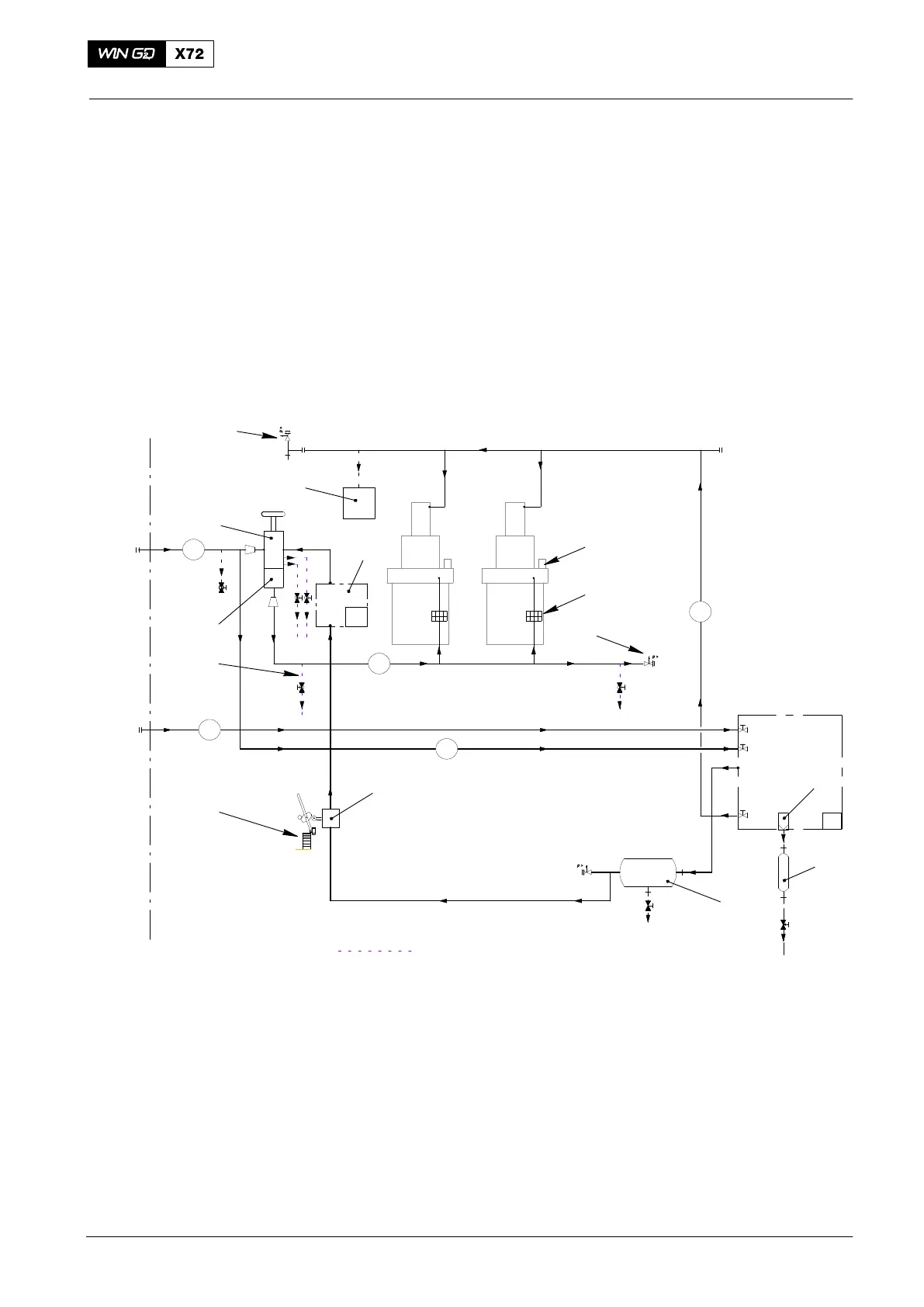
The starting air system is shown in the schematic diagram below.
The control air supply unit and air bottle 6 supply the necessary control air for the
engine.
For more data, see the Pipe Diagram − Air System 4003-9.
You must make sure that the compressed air is clean and dry.
You must open the drain valves regularly to remove condensation from the starting air
system.
A
E
15 l
1
2
3
4
5
6
7
8
9
10
12
13
14
15
16
17
18
ENGINEPLANT
Control Air
Supply Unit
A1
A2
A3
A6
3
VENT / DRAIN
11
Fig. 1: Schematic diagram − starting and control air
1 Starting valve 10 Non-return valve
2 Flame arrestor 11 Control valve and valve unit for start
3 Pressure safety valve 12 Starting air shut-off valve
4 Air filter 13 Oil leakage return (from air spring)
5 Water bottle 14 Air spring air supply
6 Air bottle (control air supply) 15 Starting air
7 3/2-way valve (turning gear) 16 Control air (board supply)
8 Turning gear 17 Starting air pipe
9 Vent / drain 18 Starting air inlet
2014