Operation9270−1/A1
Winterthur Gas & Diesel Ltd.
22/ 28
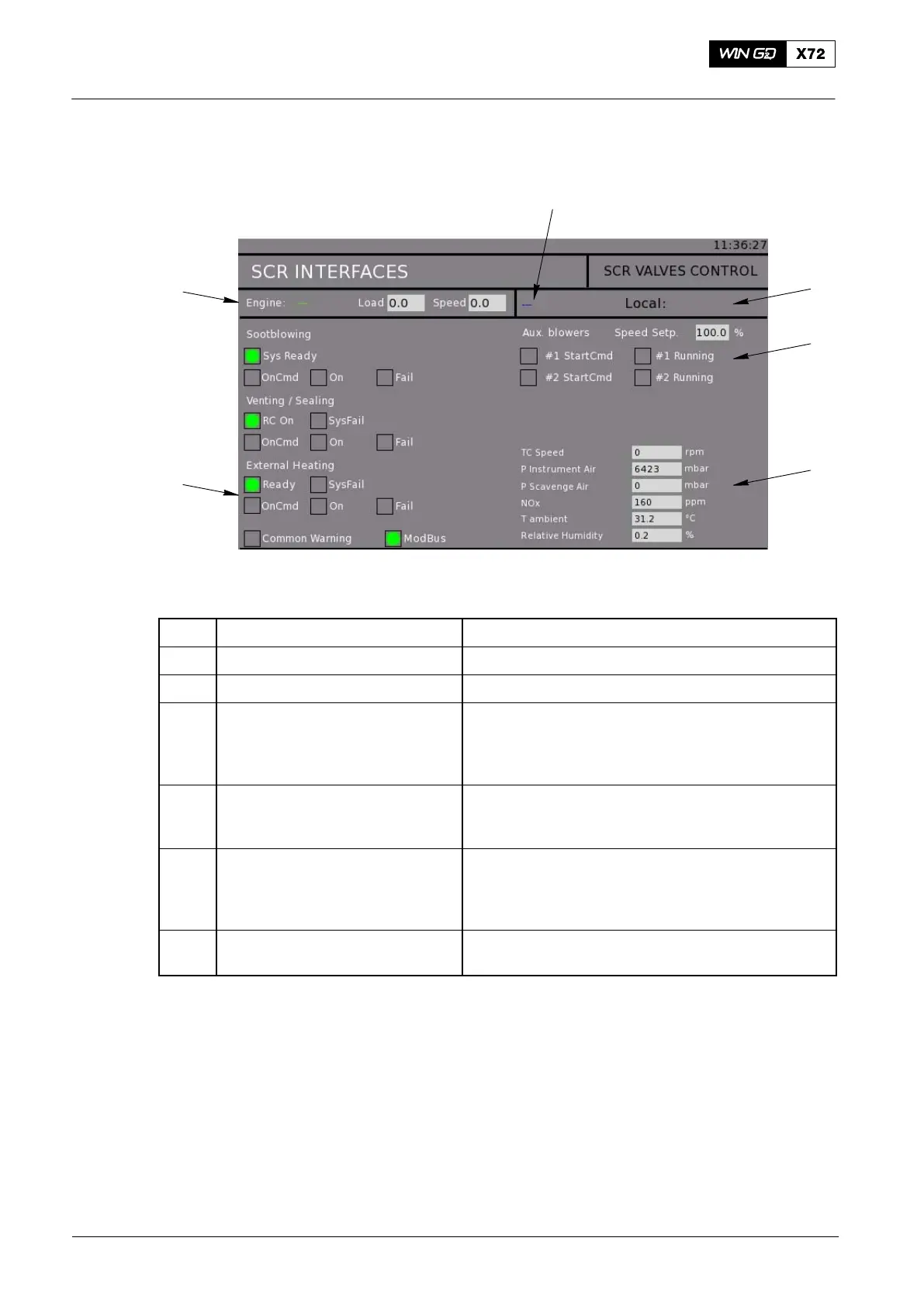
5.2.3 SCR Interface Page
WCH03734
6
1
2
5
3
4
Fig. 18: SCR Interfaces Page
Item Function Effect / Data
1 Status Indication Operator input for use of a manual value
2 Status Indication Shows the control location
3 Status Indication Shows the auxiliary blower status. During
preparation and TIER III mode the auxiliary blowers
are controlled through the SCR Valve Control
Cabinet E48.
4 Indication Shows different sensor signals from the engine
control system and from the SCR Valve Control
Cabinet E48.
5 Status Indication Shows the status of external systems. Shows data
about the sootblowing system, venting/sealing
system, external heating system and the Yara
system
6 Status Indication Shows the engine status. Shows either Running,
Tier Mode or Load/Speed.
2016−11
Selective Catalytic Reduction System