Operation
0250−1/A1
Winterthur Gas & Diesel Ltd.
1/ 2
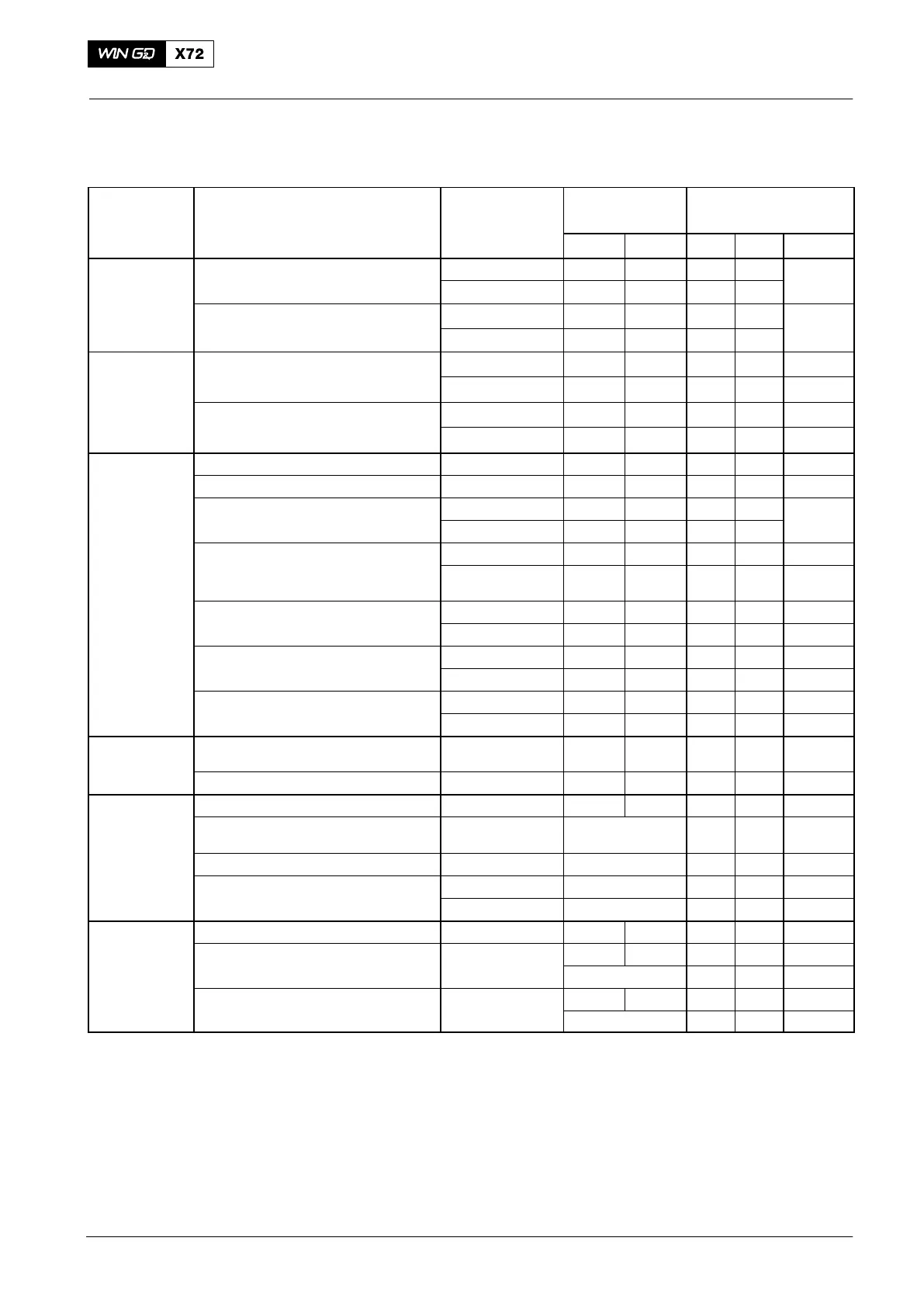
Pressure and Temperature Ranges at Continuous Service
Power MCR
Medium System Location of
Measurement
Gage Pressure
[bar]
Temperature
[_C]
Min. Max. Min. Max. Diff.
Fresh Water Cylinder cooling Inlet 4.0 5.0 65 − max.
Outlet each cylinder − − 85 95 15
SAC, low temperature circuit LT Inlet 2.0 4.0 25 36 Note (3)
(single-stage scavenge air cooler) Outlet − − − 80
Crosshead
lubricating oil
(see Note 5)
Crosshead bearing (for engines
rated in the speed range:
66.0 rpm ≤ CMCR speed ≤ 70.5 rpm
Inlet 11.0 13.0 40 50 −
Outlet − − − −
Crosshead bearing (for engines
rated in the speed range:
70.5 rpm < CMCR speed ≤ 75.0 rpm
Inlet 7.0 9.0 40 50 −
Outlet − − − −
Lubricating Oil Servo oil Pumps inlet − − − − −
Main bearing oil Inlet 4.0 5.0 40 50 −
Piston cooling oil Inlet 4.0 5.0 40 50 max.
Outlet − − − 80 30
Torsional vibration damper
(steel spring damper)
Supply 4.0 5.0 − − −
Damper inlet 2.8
Note (6)
5.0
Note (6)
− − −
Axial vibration damper
(chamber pressure)
Supply 4.0 5.0 − − −
Monitoring 1.7 − − − −
Turbocharger bearing oil (ABB, A100L type) Inlet 1.0 2.5 − − −
(with internal oil supply) Housing outlet − − − 110 −
Turbocharger bearing oil (MHI, MET type) Inlet 0.7 1.5 − − −
Housing outlet − − − 85 −
Fuel Supply unit Inlet (fuel pump) 7.0
Note (1)
10.0
Note (2)
− 150 −
Downstream of pressure retaining valve Return (fuel pump) 3.0 5.0 − − −
Scavenge Air Scavenge air cooler (SAC) Downstream of SAC 25 80 −
Intake from engine room (pressure
decrease)
Air filter / silencer max. 10 mbar − − −
Intake from outboard (pressure decrease) Ducting and filter max. 20 mbar − − −
SAC (pressure decrease) new SAC max. 30 mbar − − −
fouled SAC
max. 50 mbar
− − −
Air Starting air Engine inlet 12 25 / 30 − − −
Control air Engine inlet 6.0 7.5 − − −
Usual 6.5 − − −
Air spring of exhaust valve Main distributor 6.0 7.5 − − −
Usual 6.5 − − −
Operating Data Sheet
2017−04