Operation0250−1/A1
Winterthur Gas & Diesel Ltd.
2/ 2
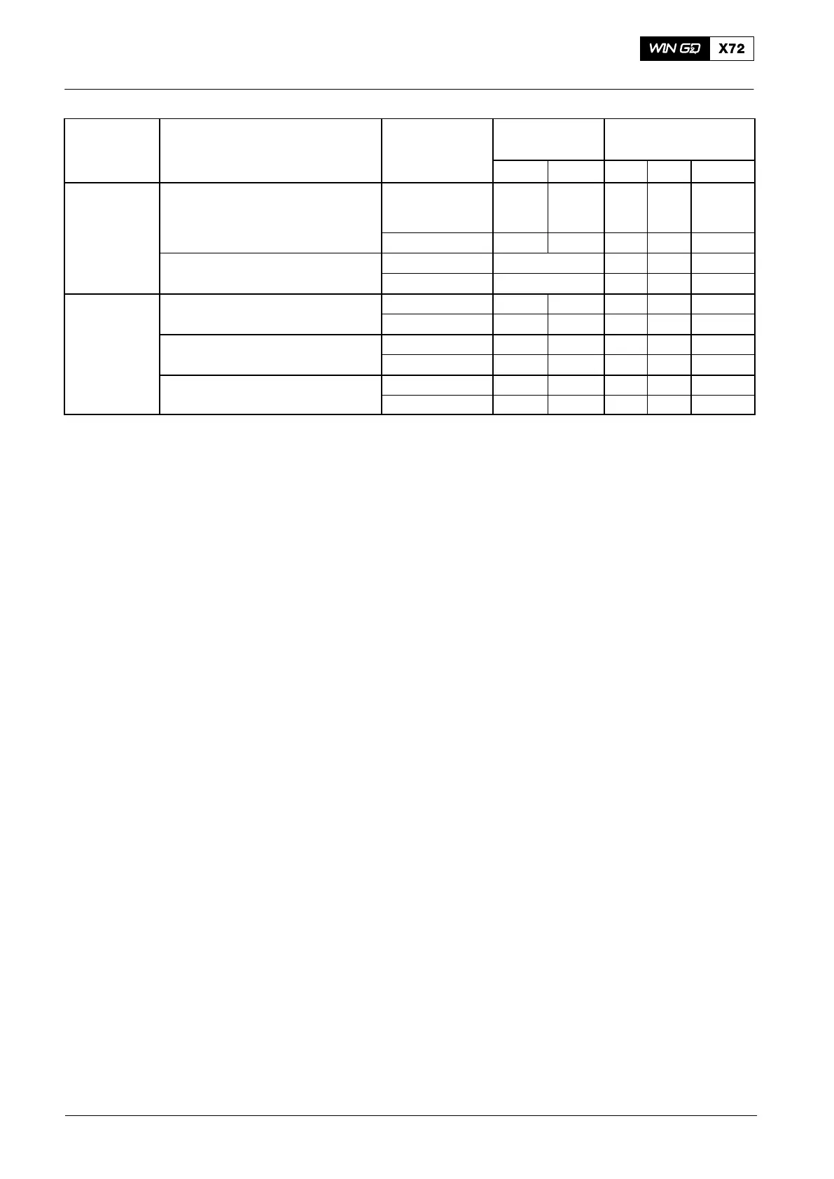
Medium System Location of
Measurement
Gage Pressure
[bar]
Temperature
[_C]
Min. Max. Min. Max. Diff.
Exhaust Gas Receiver Downstream of
each cylinder
− − − 515
Tolerance
±50
Note (4)
Turbocharger inlet − − − 515 −
Manifold downsteam of turbocharger new max. 30 mbar − − −
fouled max. 50 mbar − − −
TC Bearing Oil A100 (on engine lube oil system) Inlet 1.0 2.5 − −
Outlet − 110 −
A100 (with independent lube oil system) Inlet 1.3 2.5 − 85 −
Outlet − 130 −
MET Inlet 0.7 1.5 − −
Outlet − 85 −
For the limits of the alarm, slow-down and shutdown signals see 0250−2.
Notes:
(1) At 100% engine load.
(2) At stand-by condition; during commissioning of the fuel system, the fuel
pressure at the inlet of the fuel pumps is adjusted to 10 bar.
(3) The water flow must be in the specified limits (scavenge air cooler
specification).
(4) Maximum temperature difference between the cylinders
(5) This data is applicable only to engines with a CMCR in the range between:
D more than or equal to 66.0 rpm (CMCR speed ≥ 66.0 rpm) and
less than or equal to 70.5 rpm (CMCR speed ≤ 70.5 rpm)
D more than 70.5 rpm (CMCR speed > 70.5 rpm) and
less than or equal to 75.0 rpm (CMCR speed ≤ 75.0 rpm)
For these engines an external crosshead lubricating oil booster pump is
installed.
(6) The alarm value can be different. For the applicable setting value, refer to
the specification of the damper manufacturer.
Operating Data Sheet
2017−04