Maintenance
1132−2/A2
Winterthur Gas & Diesel Ltd.
3/ 19
2. Main Bearing Cover
(No. 2 to No. #) −
Removal
Note: This procedure is for engines
where the supply unit is near the
middle of the fuel side on engines
with 9 to 12 cylinders. For engines
with 6 to 8 cylinders, the
procedure can look different
because the supply unit is in a
different position on the engine.
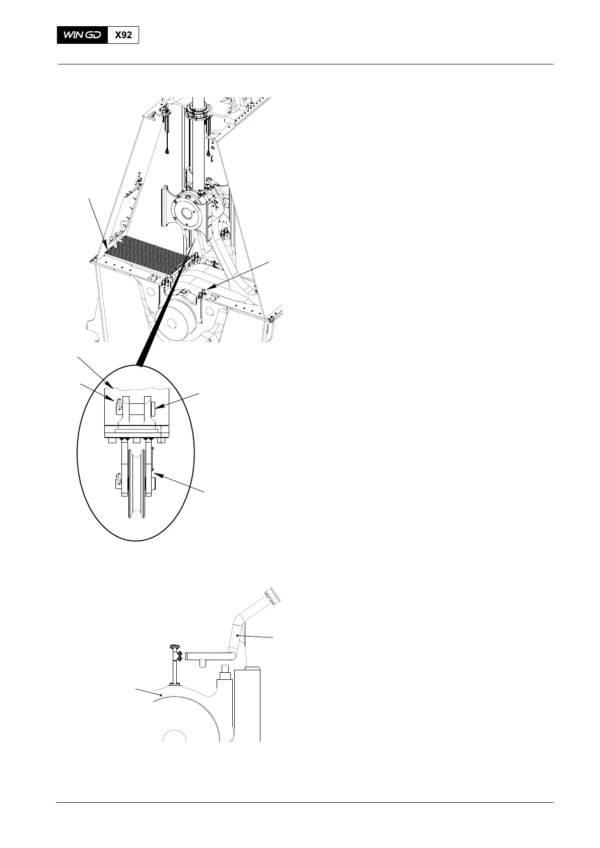
1) Put the the platform (94143, Fig.1) in
position in the column.
2) Use the feeler gauge 94123 to do a
check of the bearing clearance, refer to
0330−1.
3) Remove the round nuts (1), refer to
1132−1.
4) Attach the deviation pipe 94117B to the
column.
5) Remove the oil pipe (1, Fig.2) from the
main bearing cover (2).
2016
Main Bearing − Removal and Installation
Fig. 1
94143
1
94117
4
3
2
Fig. 2
WCH03021
1
2