Maintenance1132−2/A2
Winterthur Gas & Diesel Ltd.
4/ 19
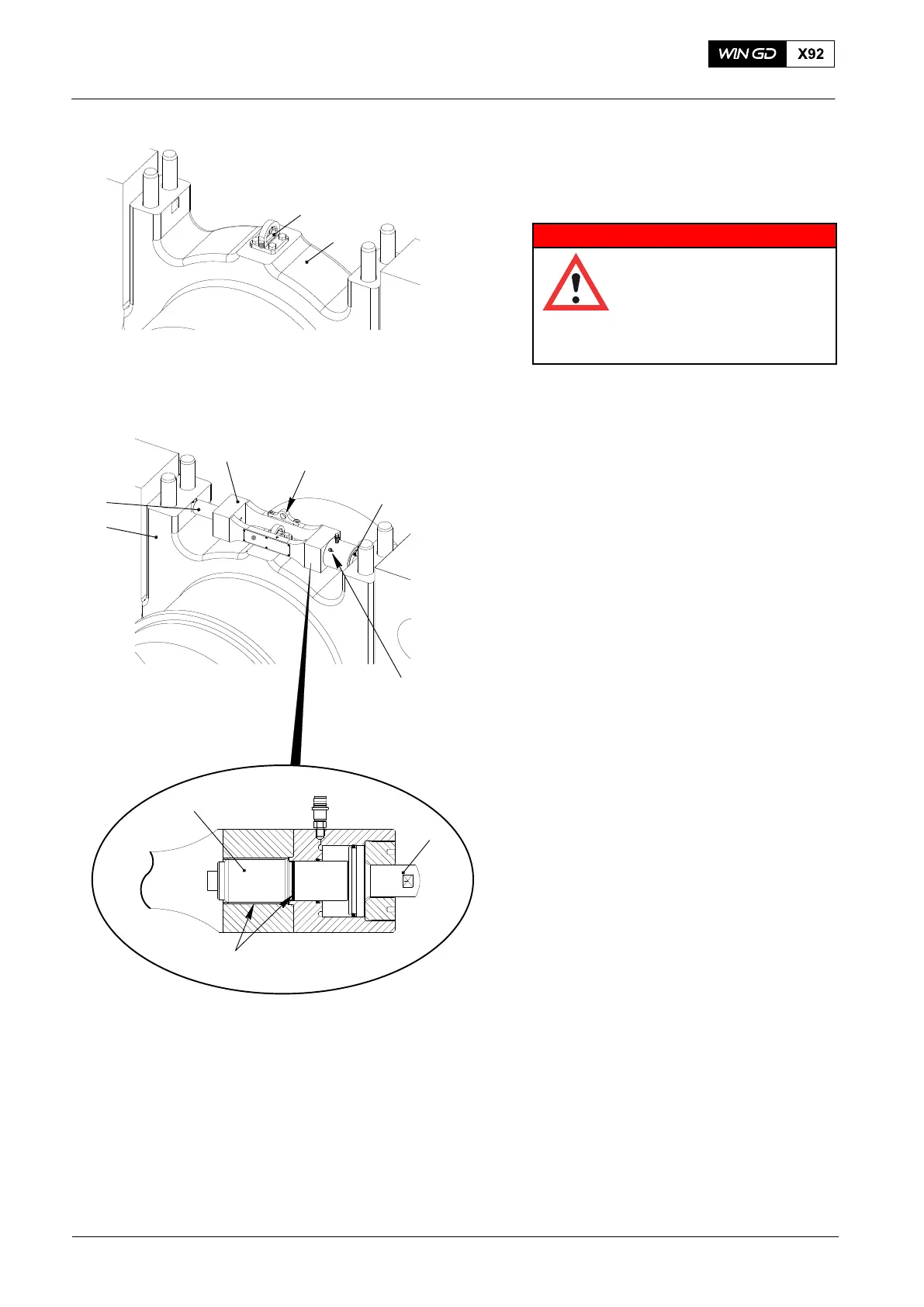
6) Install the lug (94116C, Fig. 3) on the
main bearing cover (1).
7) Make sure that the thrust device
(94110) is clean.
WARNING
Injury Hazard: The thrust
device has a WLL of only
70 kg. Do not use the
thrust device 94110 to lift
the bearing cover. Injury to
personnel can occur.
Note: Use the lifting plate (4) only to
move and install the thrust device
(94110).
8) Put the thrust device 94110 in position
on the bearing cover (1).
9) Move the plate (2) to its stowage
position.
10) Apply copper paste to the thread and
the surface of the screw (5).
11) Open the vent screw (4) and make sure
that the piston (3) is fully engaged.
12) Make sure that the tappet (6) and the
piston (3) fully engage with the cutouts
of the main bearing cover (1).
13) Connect the HP oil pump 94931 to the
thrust device 94110, refer to 9403−2.
14) Operate the HP oil pump.
15) When oil that has no air flows out,
close the vent screw (4).
16) Slowly increase the pressure to
840 bar.
17) Manually tighten the screw (5).
18) Release the pressure to zero.
19) Disconnect the HP hose from the thrust
device (94110).
2016
Removal and Fitting of a Main Bearing
Fig. 3
94116C
1
WCH03014
WCH03014
94110
1
2
5
Copper Paste
4
3
3
6
WCH03014