Maintenance
3303−5/A2
Winterthur Gas & Diesel Ltd.
5/ 8
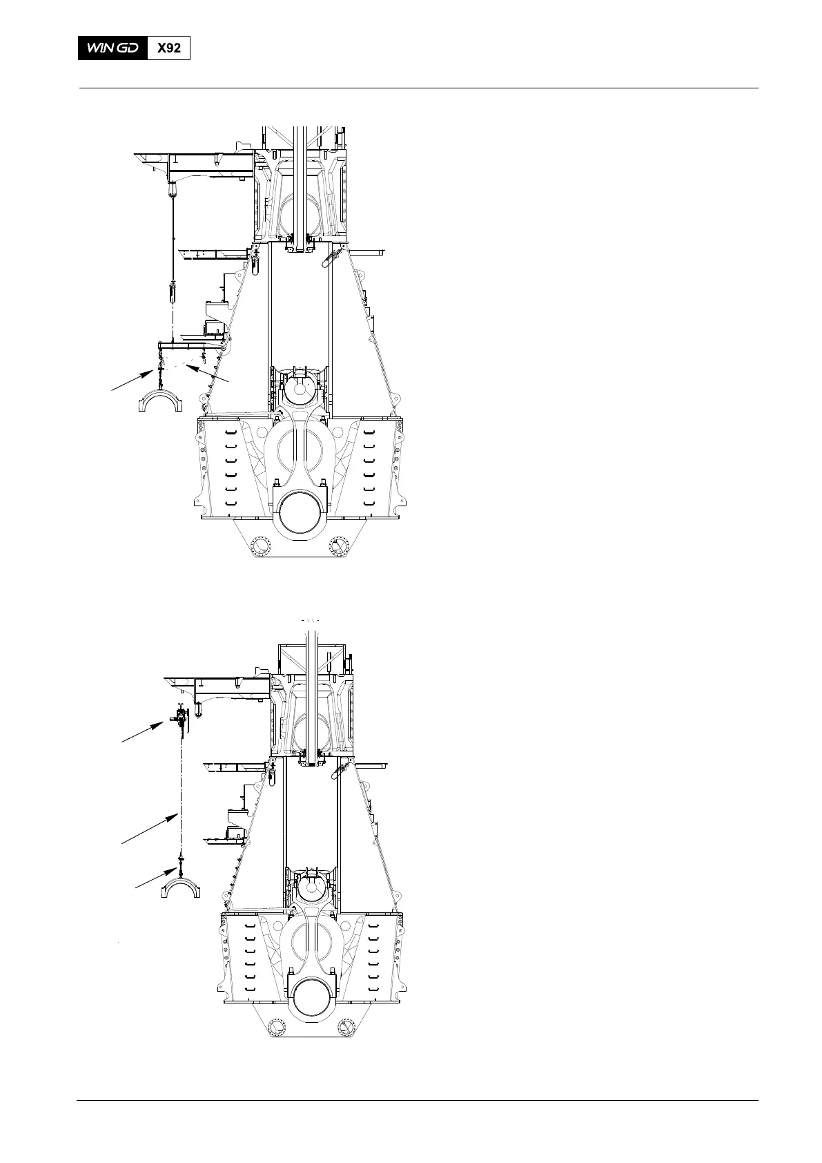
18) Operate the manual ratchets (H1, H2,
Fig. 8) to move the bearing cover
directly below (H2).
19) Remove the manual ratchet (H1).
20) Operate the manual ratchet (H2) to
lower the bearing cover on to an
applicable surface.
21) Remove the manual ratchet (H2).
22) Remove the support (94116D, refer to
Fig. 3) as follows:
a) Attach the sling (94039−015) to
the support (94116D).
b) Attach the chain block (H3) to the
shackle (94019P) and the sling
(94039−002).
c) Make sure that the chain blocks
(H5, H3) hold the weight of the
support (94116D).
d) Remove the pin (1).
e) Operate the chain blocks (H5, H3)
to lower the support (94116D) on
to an applicable surface.
f) Remove the support from the sling
(94039−002) and the chain
block (H3).
g) Remove the chain block (H5) from
the shackle (94019P).
23) Attach the trolley (94015−008, Fig. 9) to
the gallery.
24) Attach the chain block (H5) to the
trolley (94015−008) and the bearing
cover.
25) Operate the chain block (H5) to lift the
bearing cover .
26) Move the trolley (94015−008) a
sufficient distance to the engine room
crane.
3. Installation
1) Make sure that the bearing cover has
no damage.
2) Attach the bearing cover to the chain
block (H5).
3) Move the trolley (94015−008) a
sufficient distance to the applicable
position at the engine.
4) Operate the chain block (H5) to lower
the bearing cover on an applicable
surface.
5) Remove the chain block (H5 and the
trolley (94015−008).
2017
Top End Bearing Cover − Removal, Inspection and Installation
H2
WCH03784
H1
Fig. 8
WCH03784
94015−008
94015−008
Fig. 9
94325
94325