Maintenance
5556−1/A1
Winterthur Gas & Diesel Ltd.
9/ 18
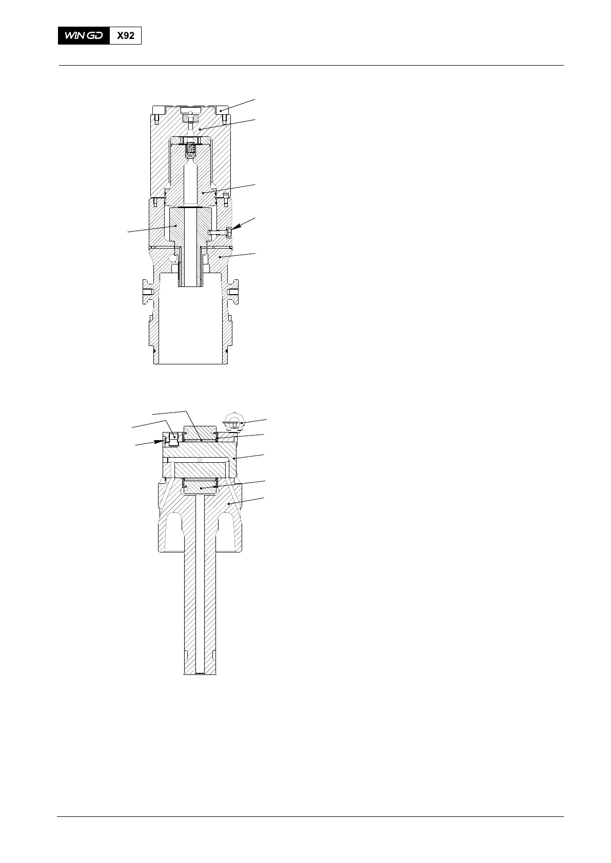
7) Put oil on lower part of the non return
valve (3).
8) Carefully put the assembled non-return
valve (3, Fig. 12) into the upper
housing (5).
9) Put the pump cover (2) in position on
the upper housing (5).
10) Apply Never Seez NSBT to the threads
and to the contact surface of the heads
of the 12 bolts (1).
11) Tighten the 12 bolts (1) to the
sequence and value given in 0352−1.
4.3 Guide Piston − Assemble
1) Clean all parts of the guide piston (5,
Fig. 13) and assemble all parts oiled.
2) Put oil on the flanks of the roller (4).
3) Put the roller (4), bush (8) and the two
pressure discs (2) in the guide
piston (5).
4) Put the pin (7) into the guide piston (5)
and tighten it (counterclockwise) with
60 Nm.
5) Align the groove in the the roller pin (3)
with the pin (7).
6) Push the roller pin (3) into the guide
piston (2) and the roller (4).
7) Attach the circlip (6) to hold the roller
pin (3) in position.
Fuel Pump: Disassemble, Assemble
2015
4
1
2
3
5
6
Fig. 12
WCH03053
Fig. 13
6
3
5
4
1
2
7
8
WCH03053