Maintenance
5556−1/A1
Winterthur Gas & Diesel Ltd.
11/ 18
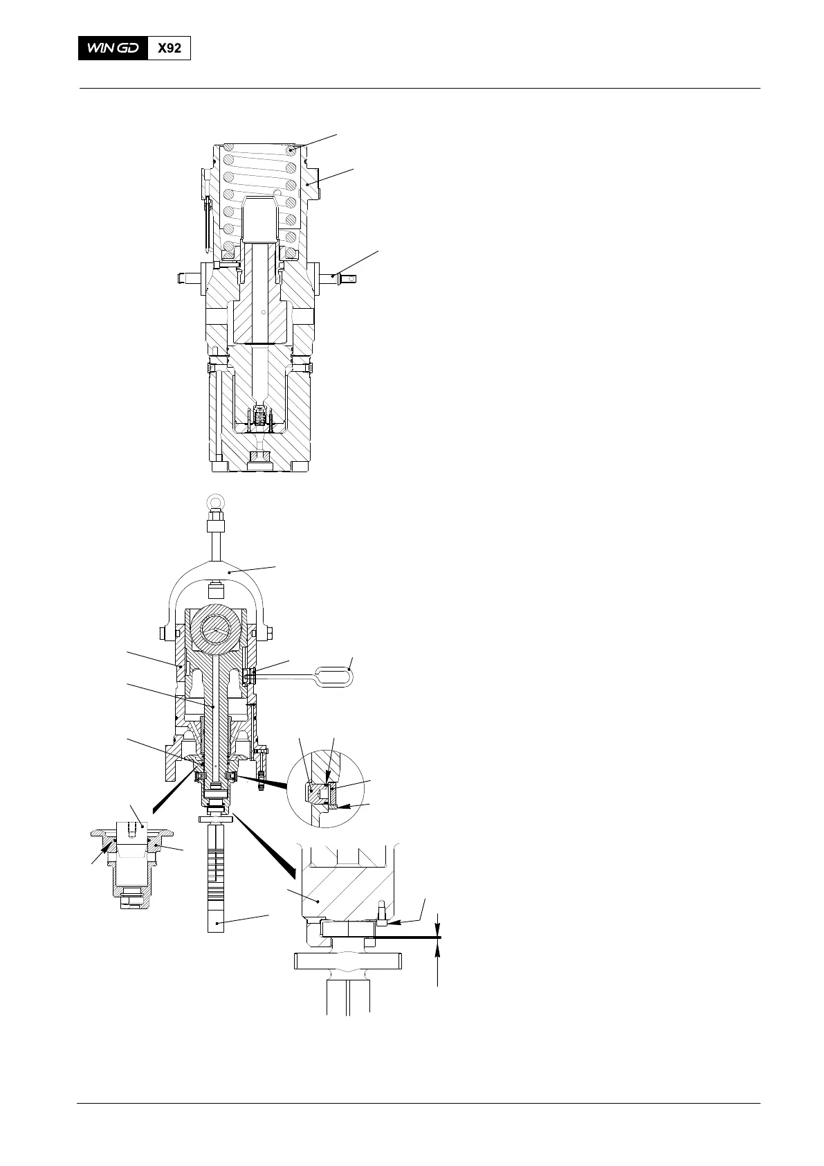
16) Move the toothed rack (3, Fig. 17) to
the middle position.
17) Put the compression spring (1) in
position in the upper housing (2).
4.5 Lower Housing − Assemble
1) Attach the spindle press (94551) to the
lower housing (9, Fig 18).
2) Put a new O-ring seal on the guide
pin (1).
3) Put the assembled guide piston (8) in
the lower housing (9). Make sure that
the groove in the guide piston aligns
with the bore in the lower housing.
4) Use the handle (94009−M10) to install
the guide pin (4).
5) Use the mandrel (94597) to install a
new seal (10) to the lower spring carrier
(7).
6) Put the lower spring carrier (7) in
position on the guide piston (8).
7) Put new O-rings (3) on the connection
pins (2).
8) Put the connection pins (2) through the
bores in the upper spring carrier. Make
sure that the connection pins engage
with the groove in the guide piston (8).
9) Use an Allen wrench (AW 10) to tighten
the connection pins (2).
10) Attach the retaining ring (4) to the
connection pin (2).
11) Attach the circlip (5) to hold the
connection pin (2) and the retaining
ring (4) in position.
12) Lift the assembly and move it into
position above the upper housing.
13) Attach the pump plunger (6) to the
lower spring carrier (7).
14) Make sure that there is a clearance X
of between 0.12mm to 0.24mm.
15) Apply Loctite 243 on screw (11) and
torque it with 9Nm.
Fuel Pump: Disassemble, Assemble
2015
Fig. 17
Fig. 18
1
2
3
WCH03053
2
4
5
3
94551
6
WCH03053
7
9
1
8
94009−M10
94597
7
10
X
11
7