1126700 SmartPAC 2 User Manual
2-28 Installation
6. Remove the appropriate connector(s) from its socket on the ProCamPAC board (TB401
for an 8-channel ProCamPAC, TB451 and TB452 for a 16-channel ProCamPAC).
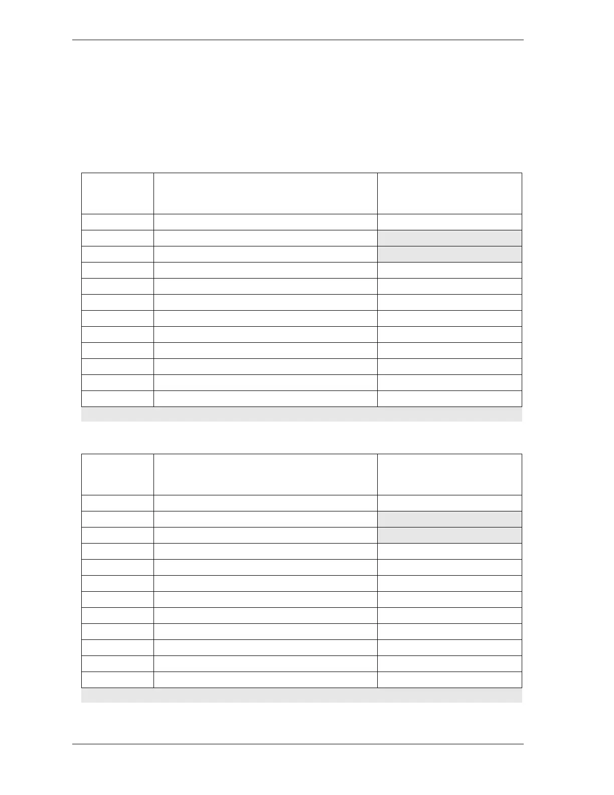
Connect wires from the 12-conductor cable(s) to the pin locations on the appropriate
terminal blocks, as shown in Table 2-7 (for the 8-channel option) or Table 2-7 and
Table 2-8 (for the 16-channel option). See also Figure 3 at the end of the manual.
Table 2-7. ProCamPAC to Cam Output Assembly TB301 Wiring, Cams 1-8
Wire
8-cam: ProCamPAC TB401 (cams 1-8)
16-cam: ProCamPAC TB451 (cams 1-8)
(Pin #)
1
st
Cam Output Board
TB301 (Pin #)
CHAS (1)
White Relay Pwr (270)
A (3)*
Black GND (269)
B (2)*
Red +5 (268) +5 Vdc (4)
Tan Ch 8 (267) Ch 8 (5)
Pink Ch 7 (266) Ch 7 (6)
Gray Ch 6 (265) Ch 6 (7)
Blue Ch 5 (264) Ch 5 (8)
Yellow Ch 4 (263) Ch 4 (9)
Orange Ch 3 (262) Ch 3 (10)
Purple Ch 2 (261) Ch 2 (11)
Brown Ch 1 (260) Ch 1 (12)
* Note that the pin numbers for A and B are out of order
Table 2-8. ProCamPAC to Cam Output Assembly TB301 Wiring, Cams 9-16
Wire -16-cam: ProCamPAC TB452 (cams 9-
16)
(Pin #)
2
nd
Cam Output Board
TB301 (Pin #)
CHAS (1)
White Relay Pwr (281)
A (3)*
Black GND (280)
B (2)*
Red +5 (279) +5 Vdc (4)
Tan Ch 16 (278) Ch 8 (5)
Pink Ch 15 (277) Ch 7 (6)
Gray Ch 14 (276) Ch 6 (7)
Blue Ch 13 (275) Ch 5 (8)
Yellow Ch 12 (274) Ch 4 (9)
Orange Ch 11 (273) Ch 3 (10)
Purple Ch 10 (272) Ch 2 (11)
Brown Ch 9 (271) Ch 1 (12)
* Note that the pin numbers for A and B are out of order