1126700 SmartPAC 2 User Manual
D-6 SmartPAC to SmartPAC 2 Upgrade
9. When you are confident that all wiring is correct, apply power and wait about a minute for
SmartPAC 2 to boot up. Then Turn the Prog/Run key to PROG.
After SmartPAC 2 has booted up, you may see a message about the resolver position
being different. Press RESET to clear the message.
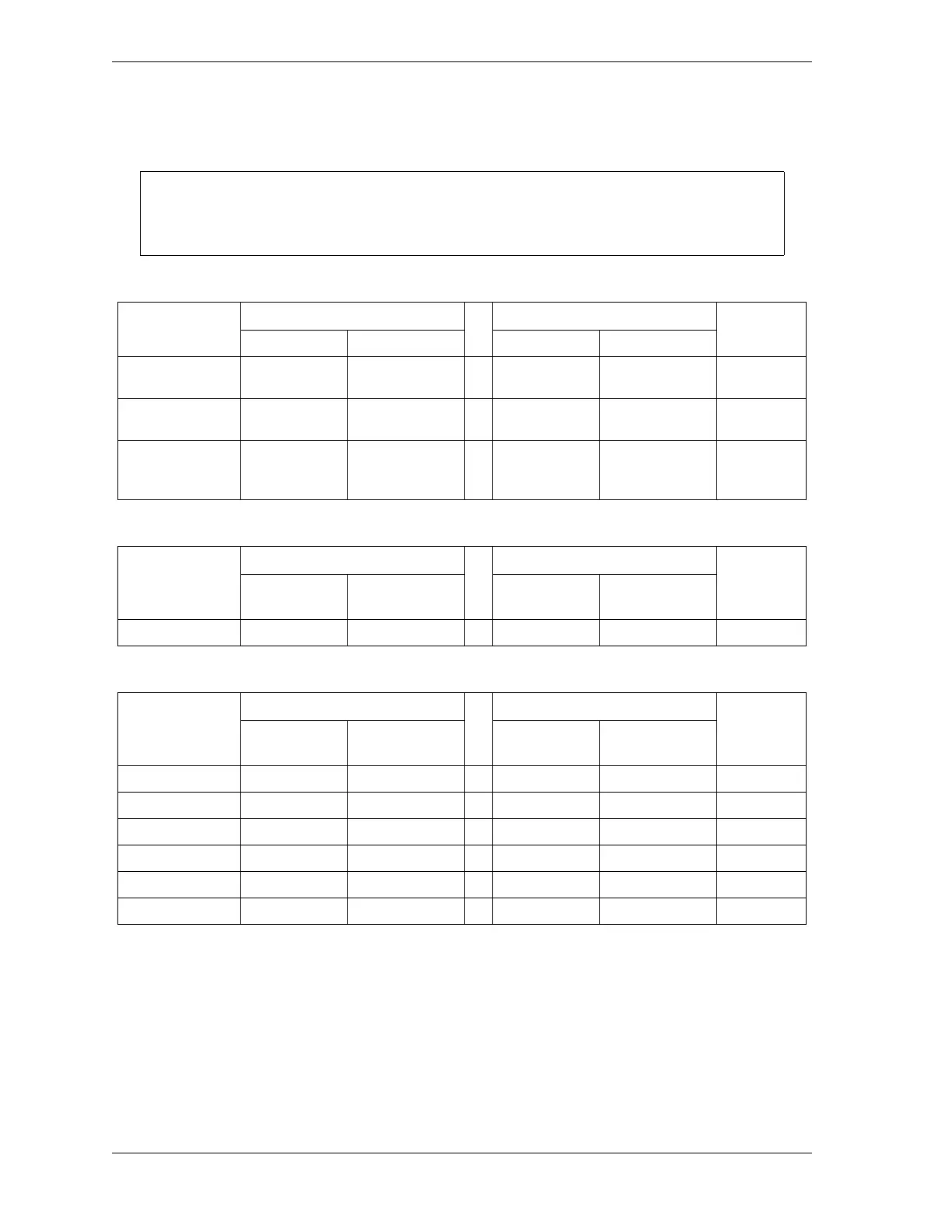
Table D-1. SmartPAC 1 to SmartPAC 2 Wiring Changes: Main Power
Original SmartPAC → SmartPAC 2
Signal Type Connector Pin Number Connector Pin Number Done (√)
L1 TB101 201
→
AC Input
L1 - High
201
L2 TB101 202
→
AC Input
L2 - Neutral
202
GND TB101 203
→
GND Setscrew
terminal or
ground stud
Table D-2. SmartPAC 1 to SmartPAC 2 Wiring Changes: Zero Cam
Original SmartPAC → SmartPAC 2
Signal Type Connector Pin Number Connector Pin Number Done (√)
ZERO CAM TB101 211
→
TB107 248
Table D-3. SmartPAC 1 to SmartPAC 2 Wiring Changes: Input Check, E-Stop, and Top Stop
Original SmartPAC → SmartPAC 2
Signal Type Connector Pin Number Connector Pin Number Done (√)
A (Input Chk.) TB101 205
→
TB102 205
B (Input Chk.) TB101 206
→
TB102 206
E-STOP TB101 207
→
TB102 207
E-STOP TB101 208
→
TB102 208
T-STOP TB101 209
→
TB102 209
T-STOP TB101 210
→
TB102 210