January 2010
2-72
Phaser 7760 Color Laser Printer
007-120
Revised
Status Indicator RAP’s
007-120 Tray 5 Misfeed (3TM)
The Tray 5 Feed Out Sensor does not detect paper after feeding from Tray 5.
Initial Actions
• Check condition and specification of paper in Tray 5.
• Check for intermittent misfeeds ensure paper type selection is correct (open tray, select
Change Description).
• Check the paper path for obstructions.
• Check for wear and clean the Tray 5 Feeder Roll, Takeaway Roll and Pinch Roll.
Procedure
Open the Left Cover and cheat the Left Cover Interlock Switch (PL 15.10). Enter Service Diag-
nostics Menu: Printer Menu > Troubleshooting > Service Tools > Printer Status Page >
hold the Up and Down buttons simultaneously > Run Service Diagnostics > OK. Block and
unblock the Tray 5 Feed Out Sensor (PL 15.10). The display changes.
YN
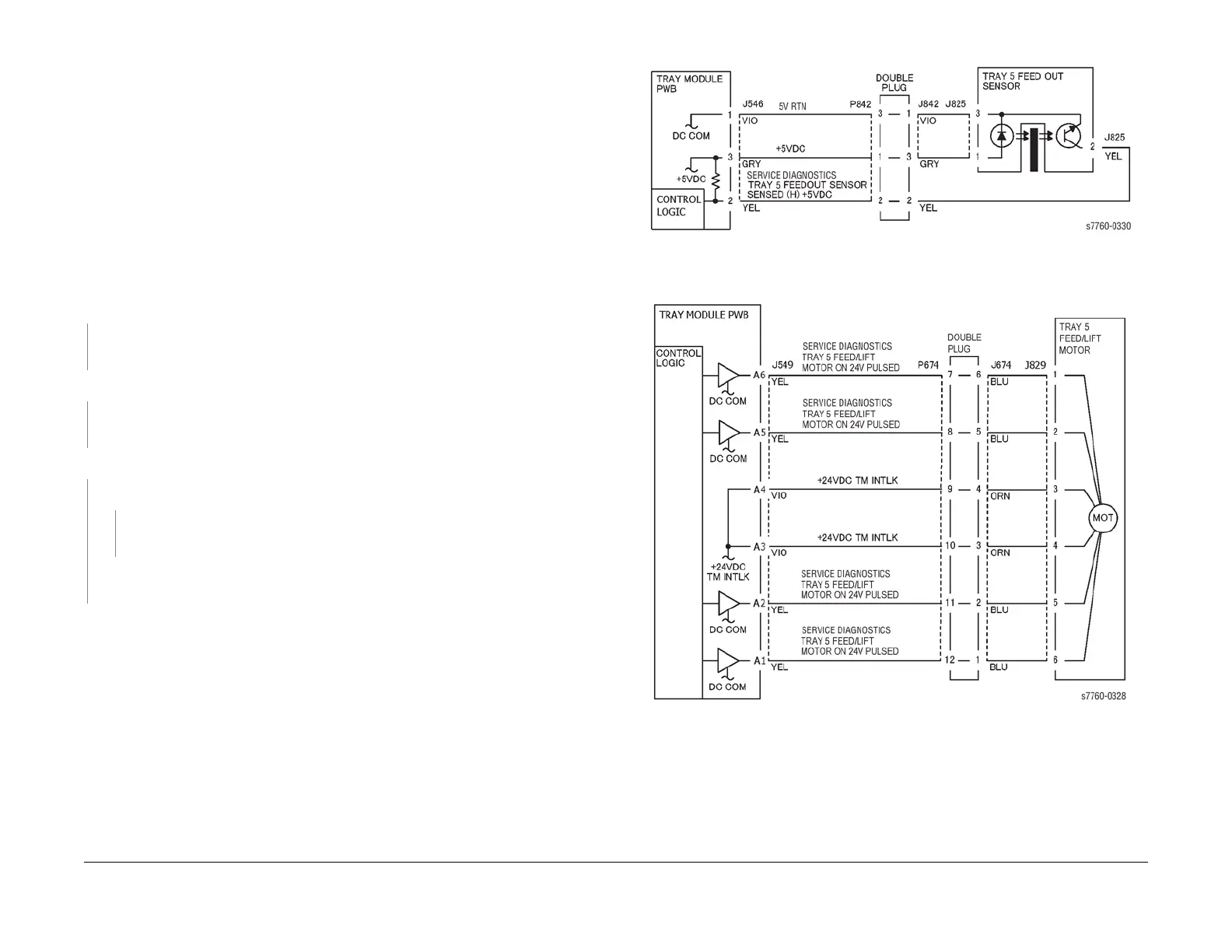
Check the circuit of the Tray 5 Feed Out Sensor (Figure 1). Refer to Section 6, Transmis-
sive Sensor Procedure for troubleshooting procedure.
Perform the Paper Feed Motors test. The Tray 5 Feed/Lift Motor (PL 2.4) energizes.
YN
Check the circuit of the Tray 5 Feed/Lift Motor (Figure 2). Refer to Section 2, OF 99-9 RAP
for troubleshooting procedure.
Perform Service Diagnostics. All 3 Takeaway Rolls (PL 15.10) rotates.
YN
Takeaway Motor 1 (PL 15.9) energizes.
YN
Check the circuit of the Takeaway Motor 1 (Figure 3). Refer to Section 2, OF 99-9
RAP for troubleshooting procedure.
Check the Takeaway Motor 1 and its associated gears (PL 15.9) for damage, contamina-
tion, or misalignment.
• Check the Tray 5 Feed/Lift Motor and its associated gears (PL 2.4) for damage, contami-
nation, or misalignment.
• Ensure that the Tray 5 Chute (PL 15.10) is properly seated and not damaged.
• Ensure that the connectors shown in the circuit diagrams (Figure 1, Figure 2, Figure 3)
are securely connected and that wires are not damaged.
• If these checks are OK, replace the Tray Module PWB (PL 15.9).
Figure 1 007-120 Tray 5 Feed Out Sensor
Figure 2 007-120 Tray 5 Feed/Lift Motor





 To Next Page