January 2010
2-5
Phaser 7760 Color Laser Printer
001-300 Left Cover (Door A) Open
Status Indicator RAP’s
Revised
001-300 Left Cover (Door A) Open
Left Cover (Door A) is open.
Procedure
Enter Service Diagnostics Menu: Printer Menu > Troubleshooting > Service Tools > Printer
Status Page > hold the Up and Down buttons simultaneously > Run Service Diagnostics >
OK.. Open and close Left Cover (PL 2.7). The display changes.
YN
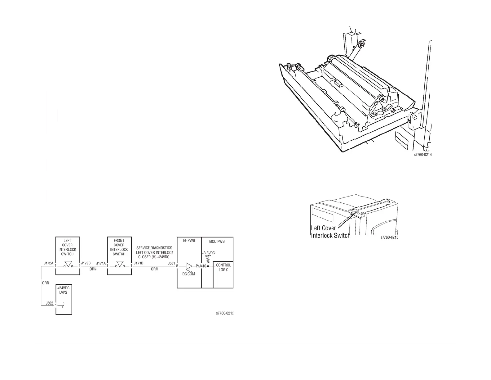
Measure the voltage between +24 LVPS J172B (Figure 1) and GND(-). +24 VDC mea-
sured.
YN
Check for +5 VDC between the gray and violet wires at P511 on the printer +5 VDC
LV PS ( PL 9.1). +5 VDC is measured.
YN
Go to Section 6, +5 VDC Low-Voltage Power Supplies RAP.
Replace the LVPS (PL 9.1).
Remove the Rear Cover (REP 14.2). Disconnect J172B (Figure 1) (from Left Cover Inter-
lock Switch (PL 2.10)). Check resistance between A1 and B1 when switch is actuated.
Resistance is less than 3 ohms.
YN
Replace the Left Cover Interlock Switch (PL 2.10).
Reinstall the Switch. Close the Left Cover (PL 2.7). Measure the voltage at J531-5 (Figure
1) on the I/F PWB. +24 VDC measured.
YN
Repair the open circuit between the +24 VDC LVPS and the I/F PWB.
Replace the Interface PWB (PL 9.1).
If the problem continues, replace the Engine Control Board (MCU PWB) (PL 13.1).
Check installation of the Cover/Actuator.
Figure 1 001-300 Left Cover Interlock Switch
Figure 2 001-300 Left Cover Interlock Actuator
Figure 3 001-300 Left Cover Interlock Switch Location