January 2010
2-6
Phaser 7760 Color Laser Printer
001-301 Left Lower Cover (Door B) Open, 001-302
Revised
Status Indicator RAP’s
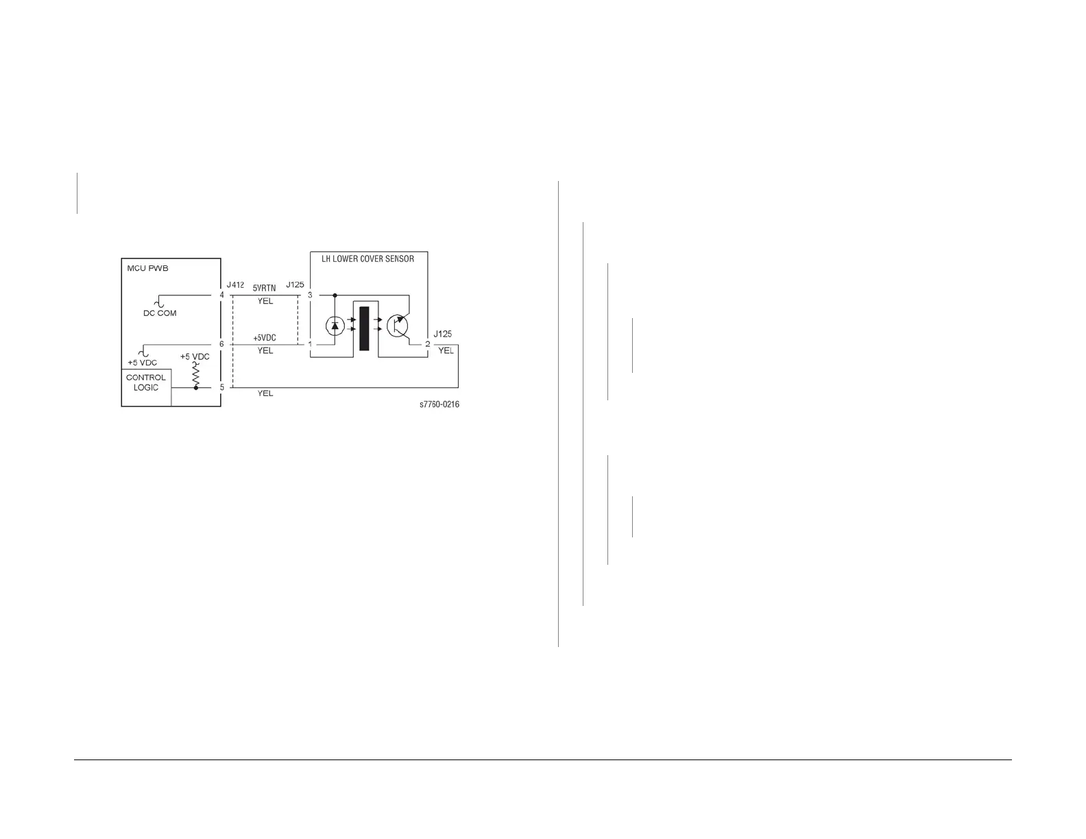
001-301 Left Lower Cover (Door B) Open
Left Lower Cover (Door B) is open
Procedure
Enter Service Diagnostics Menu: Printer Menu > Troubleshooting > Service Tools > Printer
Status Page > hold the Up and Down buttons simultaneously > Run Service Diagnostics >
OK. Open the Left Lower Cover. Actuate the Left Lower Cover Interlock Switch (PL 2.3) with a
screwdriver. The display changes.
YN
Go to Section 6, Transmissive Sensor Procedure and repair the LH Lower Cover Interlock
Switch (PL 2.3).
Check the Sensor, Actuator, and Left Lower Cover installation (PL 2.3).
Figure 1 001-301 LH Lower Cover Interlock Sensor
001-302 Front Cover Door Open
Front Cover Door is open.
Initial Actions
Check the operation of the Actuator and the switch for Front Cover and Right Side Cover.
Procedure
Open the Front Cover. Cheat the Front Interlock Switch (PL 10.1). 01-510 is cleared.
YN
+24 VDC is measured between the I/F PWB P/J531-1 (+) and GND (-) (Section 7, I/F
PWB, MAIN Motor, LVPS Plug/Jack Locations - Figure 16).
YN
+24 VDC is measured between the Front Interlock Switch P/J171-B1 (+) and
GND (-) (Section 7, Xerographic, Plug/Jack Locations - Figure 1).
YN
+24 VDC is measured between the Front Interlock Switch P/J171-A1 (+)
and GND (-) (refer to Section 7, Xerographic - Plug/Jack Locations - Figure
1).
YN
Repair the open circuit between the Left Cover Interlock Switch P/J172-B1
(Section 7, Exit Transport Assembly - Plug/Jack Locations - Figure 7) and
the Front Interlock Switch P/J171-A1.
Replace the Front Interlock Switch (PL 10.1).
+24 VDC is measured between the RH Cover Interlock Switch P/J173-B1 (+)
and GND (-) (Section 7, Outlet Panel Assembly - Plug/Jack Locations - Figure
13).
YN
+24 VDC is measured between the RH Cover Interlock Switch P/J173-A1
(+) and GND (-).
YN
Repair the open circuit between the Front Interlock Switch P/J171-B1 and
the RH Cover Interlock Switch P/J173-A1.
Replace the RH Cover Interlock Switch (PL 10.1).
Check the wire for an open circuit between the RH Cover Interlock Switch P/J173-B1
and P/J531-1 on the I/F PWB (Figure 12 - HVPS, +24V LVPS - Plug/Jack Locations)
Replace the I/F PWB (PL 9.1).
If the problem continues, replace the Engine Control Board (MCU PWB) (PL 13.1).
Check installation of the Cover/Actuator (PL 10.1).