January 2010
2-7
Phaser 7760 Color Laser Printer
001-302 Front Cover Door, 001-303 Tray Module
Status Indicator RAP’s
Revised
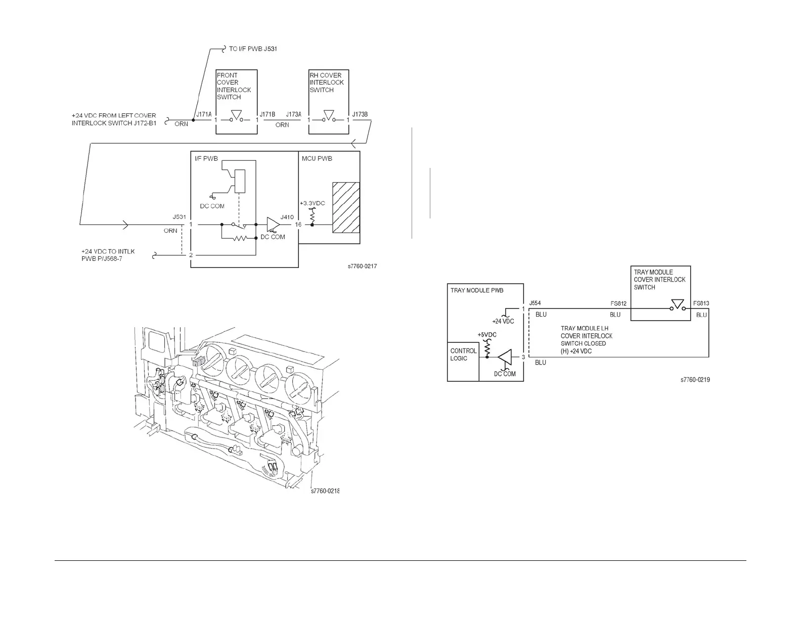
Figure 1 001-302 Front Cover/Right Cover Interlock
Figure 2 001-302 Front Interlock Switch Location
001-303 Tray Module Left Door (Door C) Open
Tray Module Left Door (Door C) is open.
Procedure
Enter Service Diagnostics Menu: Printer Menu > Troubleshooting > Service Tools > Printer
Status Page > hold the Up and Down buttons simultaneously > Run Service Diagnostics >
OK. Actuate the Tray Module LH Cover Interlock Switch (PL 16.13 TTM, PL 15.10 3TM) with a
screwdriver. The display changes.
YN
Check voltage between Tray Module PWB P/J554-3(+) and GND(-) (Section 7, TT Module
(rear); Figure 26 - 3T Module (rear) - Plug/Jack Locations - Figure 25). +24 VDC is mea-
sured.
YN
Check the wires from the Tray Module PWB P/J554-3 (Section 7, 3T Module (rear) -
Plug/Jack Locations - Figure 26) to Tray Module Cover Interlock Switch FS813 for
damage. If the wires are good, replace the Tray Module Cover Interlock Switch (PL
16.13 TTM, PL 15.10 3TM).
Replace Tray Module PWB (PL 16.15 TTM, PL 15.9 3TM).
Check the Cover Actuator and Cover installation (PL 16.13).
Figure 1 001-303 Tray Module LH Cover Interlock Switch