January 2010
2-8
Phaser 7760 Color Laser Printer
001-306 Duplex Door, 001-540.01
Revised
Status Indicator RAP’s
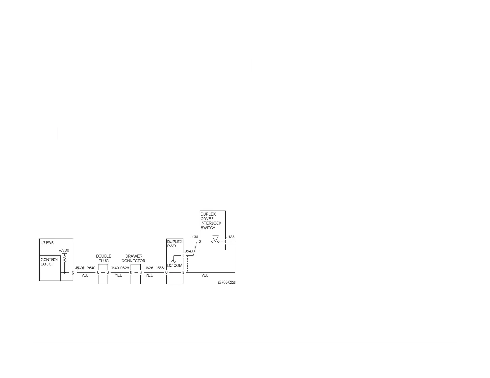
001-306 Duplex Door
Duplex Door (Door D) is open.
Procedure
Enter Service Diagnostics Menu: Printer Menu > Troubleshooting > Service Tools > Printer
Status Page > hold the Up and Down buttons simultaneously > Run Service Diagnostics >
OK. Open the Duplex Transport. Actuate Duplex Cover Interlock Switch with a screwdriver.
The display changes.
YN
Deactuate the Duplex Cover Interlock Switch. Check voltage on the Drawer Connector
between P/J626-6 (+) and GND(-) (Section 7, Duplex Transport Assembly, Plug/Jack
Locations - Figure 4). +5 VDC is measured.
YN
Check voltage between P/J539-B6 (Section 7, I/F PWB, MAIN Motor, LVPS T11-
Plug/Jack Locations - Figure 16) on the I/F PWB and GND(-). +5 VDC is mea-
sured.
YN
Replace the I/F PWB (PL 13.1).
Check for an open circuit between P/J539-B6 on the I/F PWB and Drawer Connector
J626-6.
Check the wires between Drawer Connector between J626-6 (Section 7, Inverter Trans-
port Assembly, Plug/Jack Locations - Figure 3) and Duplex PWB P/J540-1 (Section 7,
Duplex Transport Assembly, Plug/Jack Locations - Figure 4). If the wires are good,
replace the Duplex Cover Interlock Switch.
Check the Cover Actuator and Cover installation. If there is no problem, replace the Engine
Control Board (MCU PWB) (PL 13.1).
Figure 1 001-306 Duplex Cover Interlock Switch
001-540.01 Tray 1 (MPT) Paper Size Changed
Tray 1 (MPT) Paper Size changed.
Procedure
The paper guides in Tray 1 (MPT) are adjusted against paper.
YN
Adjust the Paper Guides against paper.
Go to RAP 007-270, Tray 2 Size Sensor.