January 2010
2-386
Phaser 7760 Color Laser Printer
OF 99-7, OF 99-8
Revised
Status Indicator RAP’s
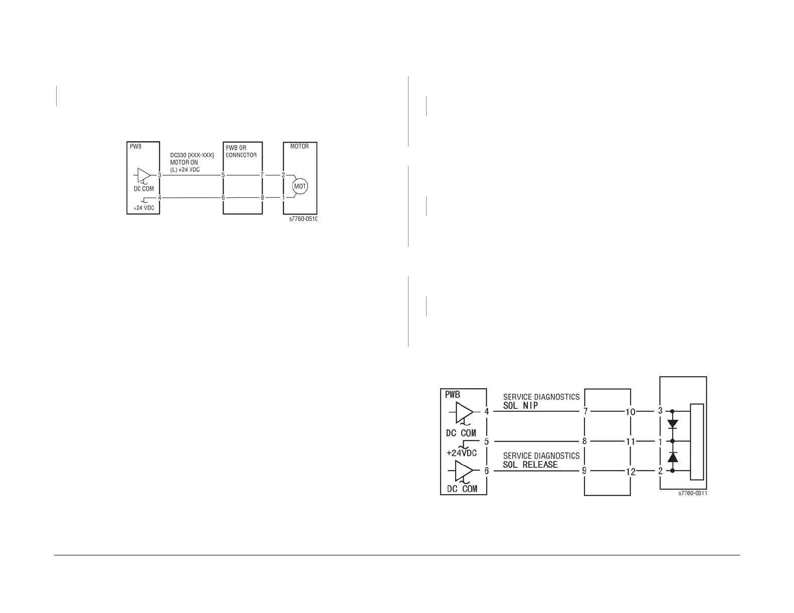
OF 99-7 2 Wire Motor On
Procedure
Turn the printer power Off. Remove the PWB connector. There is 10 Ohm’s or less mea-
sured between the connector Pin 3 and the frame.
YN
Replace the PWB.
Check the wire between the connector Pin 3 and the motor Pin 2 for a short circuit.
If the check is OK, replace the motor.
Figure 1 OF 99-7 Motor
OF 99-8 Set Gate Solenoid Open
Procedure
There is +24 VDC measured between the Nip/Release Solenoid Pin 1 (+) and GND (-).
YN
There is +24 VDC measured between the PWB Pin 5 (+) and GND(-).
YN
Check +24 VDC inputs on the PWB. If the check is OK, replace the PWB.
Check the wire between the PWB Pin 5 and the Nip/Release Solenoid Pin 1 for an open
circuit or poor contact.
There is +24 VDC measured between the PWB Pin 4 (+) and GND(-).
YN
There is +24 VDC measured between the Nip/Release Solenoid Pin 3 (+) and GND (-
).
YN
Replace the Nip/Release Solenoid.
Check the wire between the PWB Pin 4 and the Nip/Release Solenoid Pin 3 for an open
circuit and poor contact.
Follow the following when the release caused a problem.
There is +24 VDC measured between the PWB Pin 6 (+) and GND(-).
YN
There is +24 VDC measured between the Nip/Release Solenoid Pin 2 (+) and GND (-)
YN
Replace the Nip/Release Solenoid.
Check the wire between the PWB Pin 6 and the Nip/Release Solenoid Pin 2 for an open
circuit or poor contact.
Replace the PWB.
Figure 1 OF 99-8 Nip Solenoid