January 2010
2-387
Phaser 7760 Color Laser Printer
OF 99-9
Status Indicator RAP’s
Revised
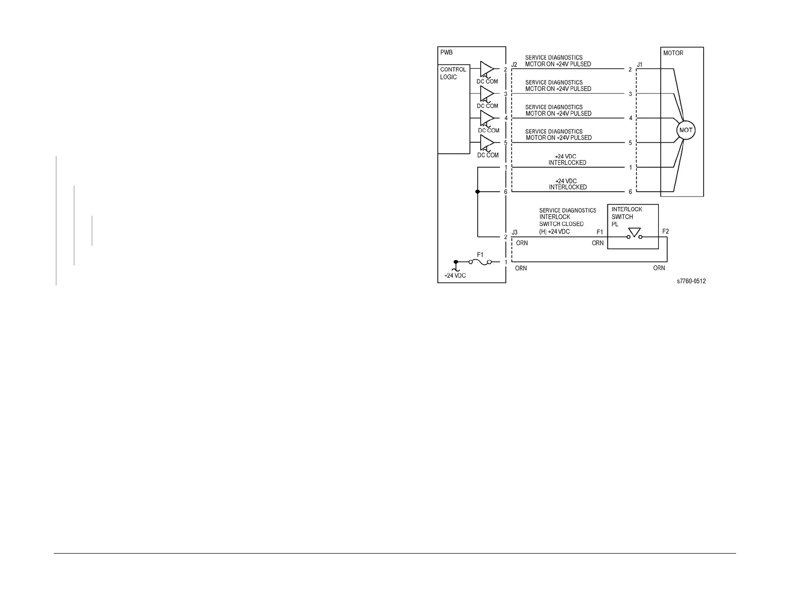
OF 99-9 Multiple Wire Motor
For use on DC motors that:
• have 1 or 2 DC power inputs
• are controlled by 2 or more drivers
• have no DC COM connections for return power
• have no specific feedback circuits
Procedure
Connect black meter lead to ground. Measure voltage at each pin of J2 (example only, refer to
the actual Circuit Diagram for the correct voltage and connector designation). +24 VDC is
measured at each pin.
YN
Disconnect J2. Measure voltage at P2-1 and P2-6 (refer to Section 7, HVPS, +24V LVPS
T10 Plug/Jack Locations - Figure 12). +24 VDC is measured.
YN
Turn the machine Off then On. Measure voltage at P2-1 and P2-6. +24 VDC is
measured.
YN
If an interlock circuit is present, check the interlock circuit. Repair as required. If
the interlock circuit is good, replace the PWB.
Check the motor wires for a short circuit. If the wires are good, replace the Motor.
Check the motor wires for obvious damage. If the wires are good, replace the Motor.
Replace the PWB.
Figure 1 OF 99-9 Motor