January 2010
2-37
Phaser 7760 Color Laser Printer
004-344, 004-345, 004-561
Status Indicator RAP’s
Revised
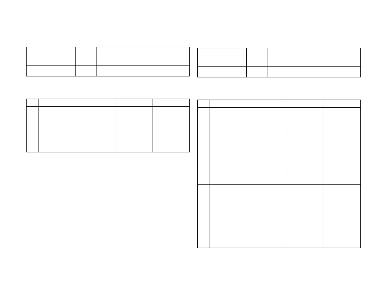
004-344 Controller Micro Pitch Fail
The micro pitch did not occur within the specified time.
Troubleshooting References
Troubleshooting Procedure
004-345, 004-561 MCU/HVPS Communication Fail
Communication error between the Engine Control Board (MCU PWB) and HVPS Control PWB.
Troubleshooting References
Troubleshooting Procedure
Table 1 References
Applicable Parts Parts List Wiring and Plug/Jack References
Engine Control Board
(MCU PWB)
PL 13.1 Section 7, Engine Control Board (MCU PWB) Plug/
Jack Locations - Figure 15
Image Processor Board PL 13.1 Section 7 - Translator/Bridge PWB’s Plug/Jack Loca-
tions - Figure 14
Table 2 Procedure
Step Actions and Questions Yes No
1 1. Cycle power to the printer to clear the
error.
2. Did the error clear?
Complete. Replace the follow-
ing order:
1. Engine Con-
trol Board
(MCU PWB)
(REP 1.2)
2. Image Proces-
sor Board
(REP 1.12)
Table 1 References
Applicable Parts Parts List Wiring and Plug/Jack References
BTR1 HVPS T11 PL 9.1 Section 7, I/F PWB, MAIN Motor, LVPS T11 Plug/
Jack Locations - Figure 16
Engine Control Board
(MCU PWB)
PL 13.1 Section 7 - Translator/Bridge PWB’s Plug/Jack Loca-
tions - Figure 14
Table 2 Procedure
Step Actions and Questions Yes No
1 Is there +5 VDC from P/J 574-5 to P/J 574-
4 on the HVPS Control PWB?
Go to step 5. Go to step 2.
2 Disconnect P/J 574.
Is there +5 VDC from J 574-5 to J 574-4?
Go to step 4. Go to step 3.
3 Is there +5 VDC from P/J 411-5 to ground? Go to Figure 1.
Check for open cir-
cuit or loose con-
nections in the 5
VDC supply wires
between P/J411,
pins 5 and 6; and P/
J574, pins 5 and 4.
Go to +5 VDC Low-
Voltage Power Sup-
plies RAP.
4Go to Figure 1. Check the wire from J411-5
to J574-5 for a short circuit to GND.
Is the wire OK?
Replace the HVPS
Control PWB (REP
1.7).
Repair the wiring
harness.
5 Switch off the power. Go to Figure 1 and
check these wires for an open or short cir-
cuit to GND:
• HVPS Control PWB P/J574-9 to MCU
PWB P/J411-1
• HVPS Control PWB P/J574-8 to MCU
PWB P/J411-2
• HVPS Control PWB P/J574-7 to MCU
PWB P/J411-3
• HVPS Control PWB P/J574-6 to MCU
PWB P/J411-4
Is the wiring OK?
Replace the Engine
Control Board
(MCU PWB) (REP
1.2).
If this does not
resolve the prob-
lem, replace the
HVPS Control PWB
(REP 1.7).
Repair the wiring
harness.