06/2014
6-17
WC 5022/5024
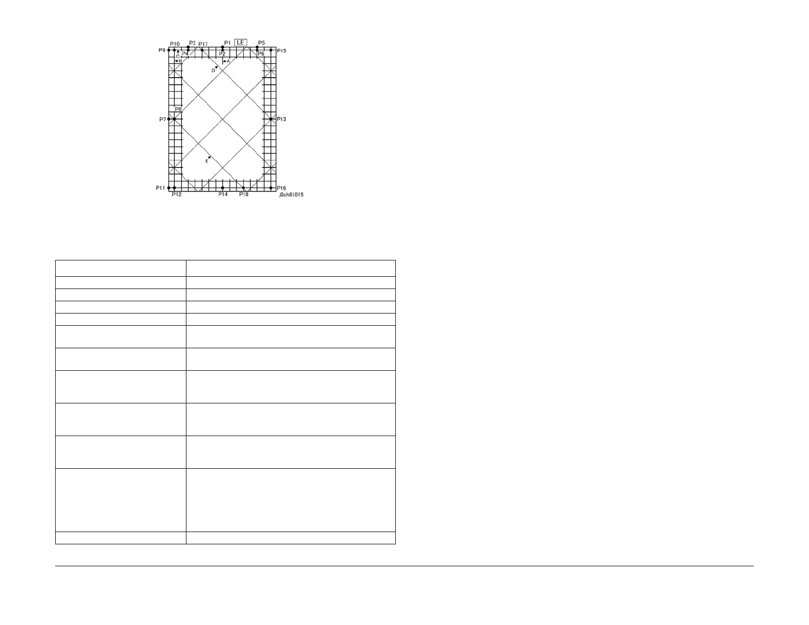
6.1.22 Alignment Specification
General
Version 1.0
Figure 1 j0ch61015
How to Measure
*1: For the reference value in the table, measure the length of the corresponding position on
the STP3600.
Table 2
Measurement Item How to Measure
Lead Regi [mm] (P1 to P2) - Reference value *1
Side Regi [mm] (P7 to P8) - Reference value *1
Lead Skew (200 mm) [mm] (P5 to P6)-(P3 to P4)
Side Skew (400 mm) [mm] (P9 to P10)-(P11 to P12)
Horizontal R/E Precision (All area)
[%]
[(P8 to P13)-280]/280x100
Vertical R/E Precision (All area)
[%]
[(P2 to P14)-400]/400x100
Perpendicularity [mm] The shift between P14 and the perpendicular line that
extends from the intersection of the straight line connect-
ing P4 and P6 and the line A.
Linearity (Vertical) (400 mm) [mm] The maximum shift between the intersections of the verti-
cal line B with the various horizontal lines and the straight
line connecting P10 and P12.
Linearity (Horizontal) (280 mm)
[mm]
The maximum shift between the intersections of the hori-
zontal line C with the various vertical lines and the
straight line connecting P10 and P15.
Linearity (Diagonal) (280 mm)
[mm]
The maximum shift between the intersections of the diag-
onal line D with the various lines and the straight line
connecting P17 and P13, or the maximum shift of the
intersections of the diagonal line E with the various lines
and the straight line connecting P8 and P18, whichever is
larger.
Trapezoid Correction [mm] (P10 to P12)-(P15 to P16)
 Loading...