06/2014
7-3
WC 5022/5024
7.1.1 Plug/Jack Location List
Wiring Data
Version 1.0
7.1.1 Plug/Jack Location List
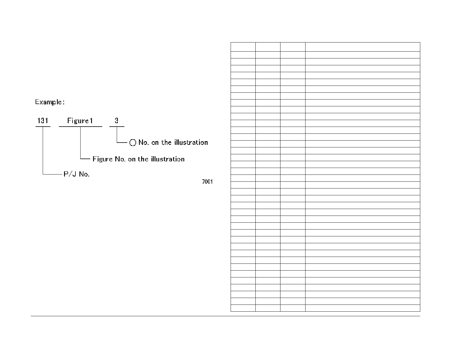
How to Use the Plug/Jack Location List
• To find which position to install specific connectors to, refer to the table ’Plug/Jack Loca-
tion List ’ for Figure No. and Item No., and then to the figure in ’Plug/Jack Positions.’
• P/J No. on ’Plug/Jack Location List’ is expressed in the four ways below:
• J250 represents Jack 250.
• P250 represents Plug 250.
• CN1 represents Connector 1.
• FS1 represents Faston Terminal 1.
Figure 1 7001
Plug/Jack Location List
Table 1 Plug/Jack Location List
P/J Fig Item Remarkes (where to Connect)
J1 8 9 AC Inlet
P/J2 3 15 UI PWB (to LCD Display)
J2 8 7 AC Inlet
J2 14 4 FAX PWB (Connect to P353)
P3 3 10 UI PWB
J3 8 1 Main Power Switch
J3 14 6 FAX PWB
P/J4 3 9 UI PWB (to One Touch Panel)
J4 8 2 Main Power Switch
J4 14 5 FAX PWB (Micro SD)
P/J5 3 8 One Touch Panel
P5 14 3 FAX PWB (Connect to J352)
J5 8 11 Main Power Switch
J6 8 10 Main Power Switch
J7 8 8 AC Inlet
P/J10 4 7 Fusing Unit
P/J100 7 4 L/H Cover Interlock Switch
P/J101A 12 2 Tray 4 Nudger Level Sensor (2TM)
P/J101B 12 2 Tray 3 Nudger Level Sensor (2TM)
P/J101C 9 2 Tray 2 Nudger Level Sensor (1TM)
P/J102 4 2 MSI No Paper Sensor
P/J102A 12 3 Tray 4 No Paper Sensor (2TM)
P/J102B 12 3 Tray 3 No Paper Sensor (2TM)
P/J102C 9 3 Tray 2 No Paper Sensor (1TM)
P/J103 4 10 Fusing Unit Exit Sensor
P/J104 4 1 Regi. Sensor
P/J105 4 3 Tray 1 No Paper Sensor
P/J108 5 1 Front Cover Switch
P/J109 7 8 Tray 1 Paper Size Switch
P123 11 6 ESS/MCU PWB
P/J130 5 3 ROS Motor
P/J140 5 6 LD PWB (8pin)
P/J160 5 5 LD PWB (2pin)
P/J201 5 7 LD PWB 24V INTLK
P/J201 7 5 Main Drive Motor (2pin)
P/J202 7 3 Main Drive Motor (8pin)
P/J203 4 6 Duplex Clutch (2pin)
P/J204 7 6 Regi. Clutch
 Loading...