ELEC
SIGNALING SYSTEM
8-31
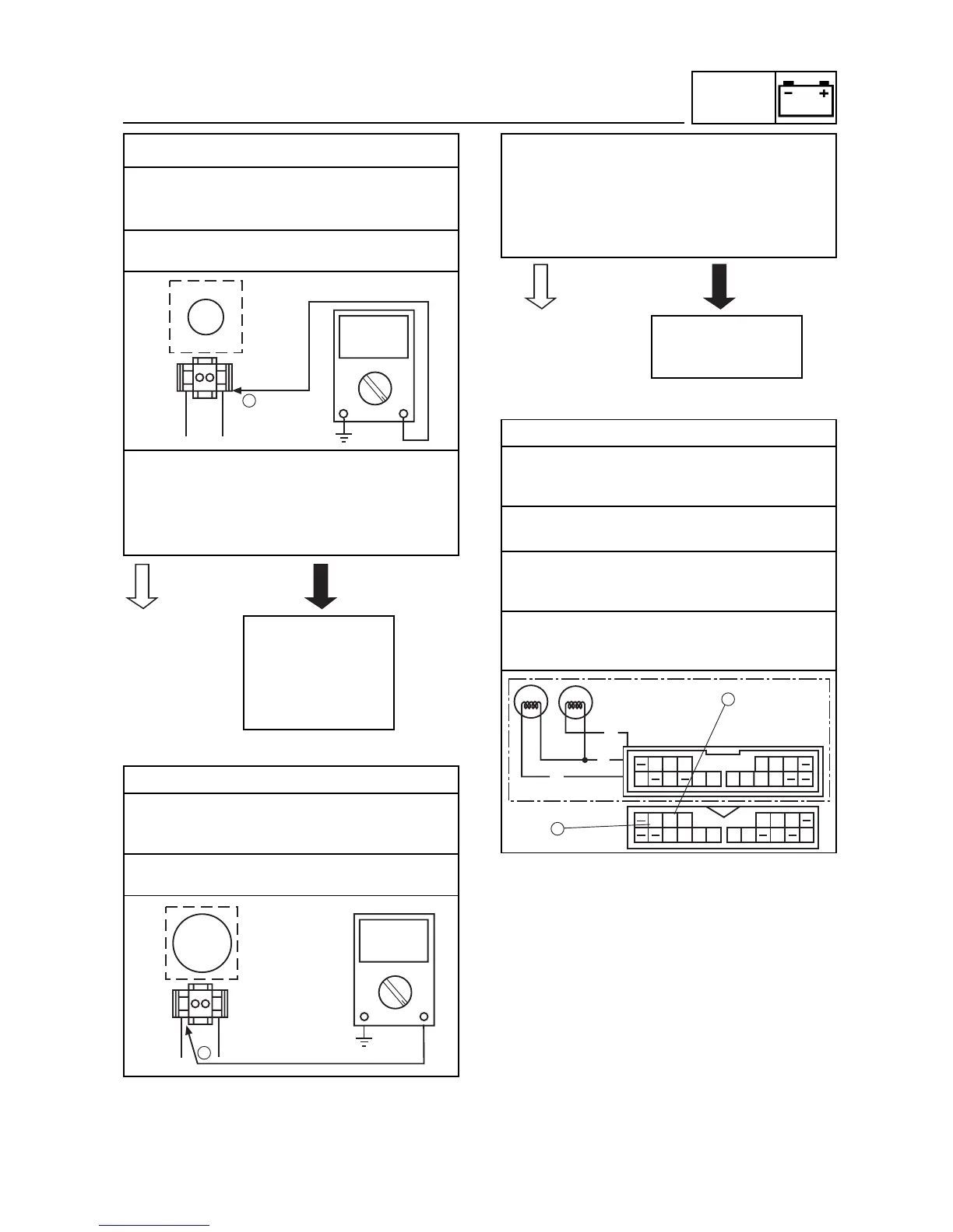
3. Voltage
• Connect the pocket tester (DC 20 V) to the
turn signal relay coupler (wire harness side)
as shown.
Positive tester probe
brown
Negative tester probe
ground
• Set the main switch to “ON”.
• Measure the voltage (DC 12 V) on brown
at the turn signal relay coupler (wire har-
ness side).
• Is the voltage within specification?
4. Voltage
• Connect the pocket tester (DC 20 V) to the
turn signal relay coupler (wire harness side)
as shown.
Positive tester probe
brown/white
Negative tester probe
ground
• Set the main switch to “ON”.
• Set the turn signal switch to “L” or “R”.
• Measure the voltage (DC 12 V) on
brown/white at the turn signal relay cou-
pler (wire harness side).
• Is the voltage within specification?
5. Voltage
• Connect the pocket tester (DC 20 V) to the
turn signal light connector or meter coupler
(wire harness side) as shown.
Turn signal light
Turn signal indicator light
Left turn signal light
Positive tester probe
chocolate
Negative tester probe
ground
Right turn signal light
Positive tester probe
dark green
Negative tester probe
ground