ELEC
SIGNALING SYSTEM
8-35
ss
WARNING
• Handle the thermo switch with special
care.
• Never subject the thermo switch to
strong shocks. If the thermo switch is
dropped, replace it.
Thermo switch
16 Nm (1.6m • kg)
Three bond sealock
®
10
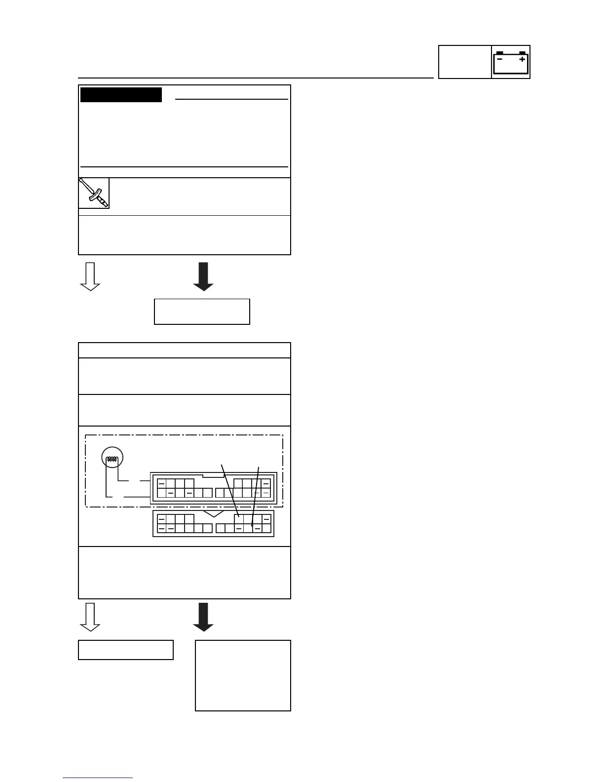
• Does the thermo switch operate properly as
described above?
3. Voltage
• Connect the pocket tester (DC 20 V) to the
meter coupler (wire harness side) as
shown.
Positive tester probe
brown
Negative tester probe
green/red
• Set the main switch to “ON”.
• Measure the voltage (DC 12 V) of brown
and green/red at the meter coupler.
• Is the voltage within specification?
Replace the thermo
switch
The wiring circuit
from the main
switch to the meter
coupler is faulty
and must be
repaired.








 To Next Page