ELEC
SIGNALING SYSTEM
8-34
• Set the main switch to “ON”.
• Measure the voltage (DC 12 V) of red/yellow
on the multi-function meter coupler (wire
harness side).
• Is the voltage within specification?
2. Speed sensor
• Connect the pocket tester (DC 20 V) to the
speed sensor coupler (wire harness side) as
shown.
Positive tester probe
blue/green
Negative tester probe
black/yellow
• Set the main switch to “ON”.
• Elevate the front wheel and slowly rotate it.
• Measure the voltage (DC 12 V) of red/yellow
and black/yellow. With each full rotation of
the front wheel, the voltage reading should
cycle from 0 V to 5 ~ 11V to 0 V to 5 ~ 11V.
• Does the voltage reading cycle correctly?
EAS00802
7. The water temperature warning light fails to
come on (CS50Z only).
1. Water temperature warning light bulb and
socket
• Check the water temperature warning light
bulb and socket for continuity.
Refer to “CHECKING THE BULBS AND
BULB SOCKETS”
• Are the water temperature warning light
bulb and socket OK?
EAS00811
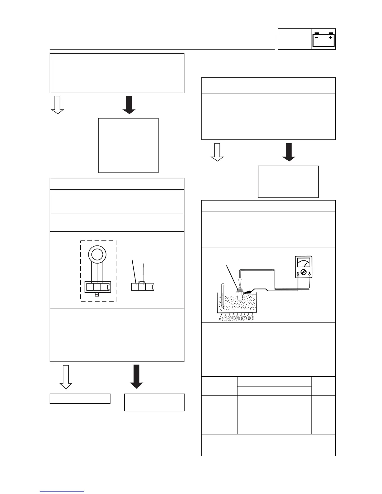
2. Thermo switch
• Remove the thermo switch from the cylin-
der head.
• Connect the pocket tester (Ω x 1) to the
thermo switch as shown.
• Immerse the thermo switch in a container
filled with coolant.
• Place a thermometer in the coolant.
• Slowly heat the coolant, then let it cool
down to the specified temperature.
• Check the thermo switch for continuity at
the temperatures indicated below.
Test step
Coolant temperature
Conti-
Thermo switch nuity
1 0 ~ 120 3°C NO
2 More than 120 3°C YES
3* 120 3°C to 113 3°C YES
4* Less than 113 3°C NO
Steps 1 & 2: Heating phase
Steps 3* & 4*: Cooling phase
The wiring circuit
from the main
switch to the multi-
function meter bulb
socket coupler (wire
harness side) is
faulty, repair it.
 Loading...