ELEC
SIGNALING SYSTEM
8-33
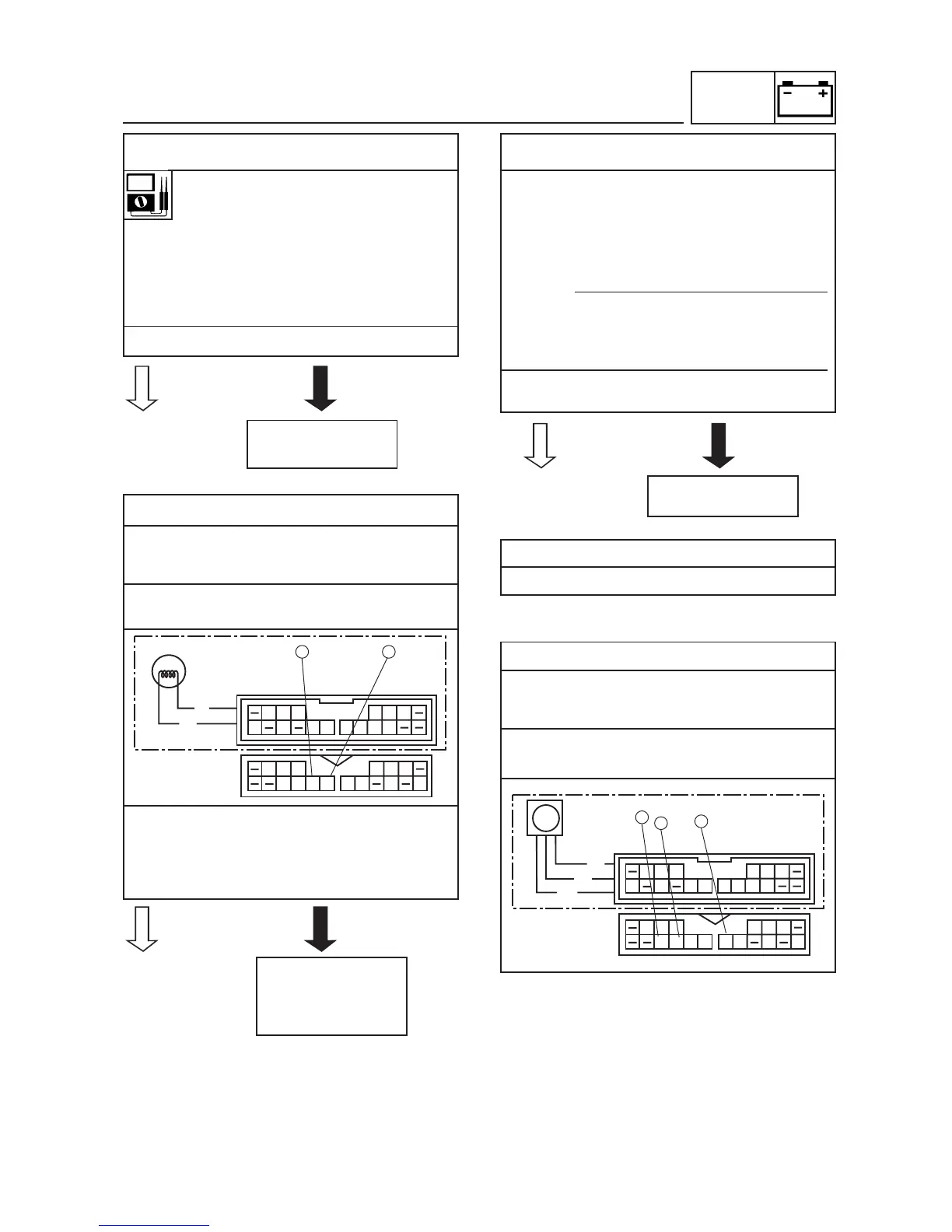
• Measure the fuel sender resistances.
Fuel sender resistance (up position
“F”)
(Ω x 1)
1.5 ~ 7.5 Ω at 20°C (68°F)
Fuel sender resistance (down posi-
tion “E”)
(Ω x 10)
90 ~ 100 Ω at 20°C (68°F)
• Is the fuel sender OK?
2. Voltage
• Connect the pocket tester (DC 20 V) to the
meter coupler (wire harness side) as
shown.
Positive tester probe
green
Negative tester probe
sky blue
• Set the main switch to “ON”.
• Measure the voltage (DC 12 V) of green
on the meter light coupler (wire harness
side).
• Is the voltage within specification?
3. Fuel level gauge
• Set the main switch to “ON”.
• Move the float up or down.
• Check that the display segments of the fuel
level gauge increase or decrease to “E” or
“F”.
NOTE:
Before reading the fuel level gauge, leave
the float in one position (either up or down)
for at least three minutes.
• Does the fuel level gauge needle move
appropriately?
4. Wiring
Check the entire signaling system’s wiring.
EAS00806
6. The speedometer fails to come on.
1. Voltage
• Connect the pocket tester (DC 20 V) to the
multi-function meter socket coupler (wire
harness side) as shown.
Positive tester probe
red/yellow
Negative tester probe
black/yellow
Replace the fuel
sender.