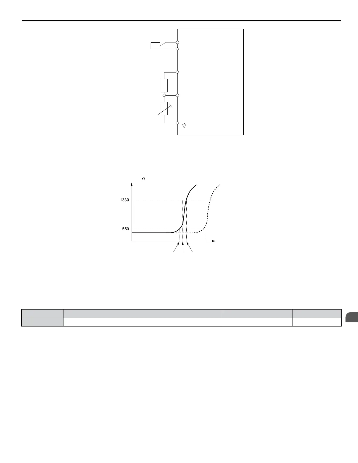
Drive
Multi-function input
PTC
thermistor
A3 (0-10 V)
AC
V+ Power supply
+10.5 Vdc,
max. 20 mA
12 kOhm
resistor
PTC external circuit
(customer supplied)
Figure 5.67 Connection of a Motor PTC
The PTC must exhibit the characteristics shown in Figure 5.68 in one motor phase. The motor overload protection of the drive
expects 3 of these PTCs to be connected in a series.
Resistance ( )
Class F
150 ºC
Class H
180 ºC
Tr: threshold value
Temperature
Tr’
Tr + 5K (oH4 Fault Level)TrTr - 5K (oH3 Alarm Level)
Figure 5.68 Motor PTC Characteristics
Set up overheat detection using a PTC using parameters L1-03, L1-04, and L1-05 as explained in the following sections.
n
L1-03: Motor Overheat Alarm Operation Selection (PTC input)
Sets the drive operation when the PTC input signal reaches the motor overheat alarm level (oH3).
No. Name Setting Range Default
L1-03 Motor Overheat Alarm Operation Selection (PTC input) 0 to 3 3
Setting 0: Ramp to Stop
The drive stops the motor using the deceleration time 1 set in parameter C1-02.
Setting 1: Coast to Stop
The drive output is switched off and the motor coasts to stop.
Setting 2: Fast Stop
The drive stops the motor using the Fast Stop time set in parameter C1-09.
Setting 3: Alarm Only
The operation is continued and an oH3 alarm is displayed on the digital operator.
n
L1-04: Motor Overheat Fault Operation Selection (PTC input)
Sets the drive operation when the PTC input signal reaches the motor overheat fault level (oH4).
5.8 L: Protection Functions
YASKAWA SIEP YAIP1U 01C AC Drive - P1000 Technical Manual
237
5
Parameter Details

 Loading...


