Digital
Operator
Display
Name Page
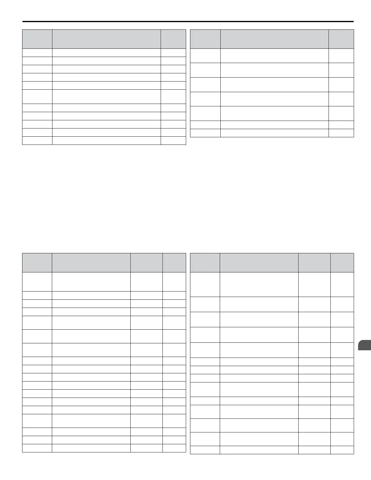
rH Dynamic Braking Resistor 306
rr Dynamic Braking Transistor 307
SC IGBT Short Circuit or Ground Fault 307
SEr Too Many Speed Search Restarts 307
TdE Time Data Error 307
THo
<4>
Thermistor Disconnect 307
TIE Time Interval Error 307
TIM Time Not Set 308
UL3 Undertorque Detection 1 308
UL4 Undertorque Detection 2 308
UL6 Motor Underload 308
Digital
Operator
Display
Name Page
UnbC
<4>
Current Unbalance 308
Uv1
<3>
Undervoltage 309
Uv2
<3>
Control Power Supply Undervoltage 309
Uv3
<3>
Soft Charge Circuit Fault 309
Uv4
<4>
Gate Drive Board Undervoltage 309
voF Output Voltage Detection Fault 310
vToL VT Overload 310
<1> Displayed as CPF00 when occurring at drive power up. When one of the faults occurs after successfully starting the drive, the display will show
CPF01.
<2> Displayed as CPF20 when occurring at drive power up. When one of the faults occurs after successfully starting the drive, the display will show
CPF21.
<3> Fault histories are not kept when CPF00, CPF01, CPF06, CPF24, oFA00, oFb00, oFC00, Uv1, Uv2, or Uv3 occur.
<4> Detected in models 4A0930 and 4A1200.
n
Minor Faults and Alarms
Refer to Table 6.5 for an overview of possible alarm codes. Conditions such as overvoltages can trip faults and alarms. It is
important to distinguish between faults and alarms to determine the proper corrective actions.
When the drive detects an alarm, the ALM indicator LED blinks and the alarm code display flashes. Most alarms trigger a
digital output programmed for alarm output (H2-oo = 10). A fault (not an alarm) is present if the ALM LED lights without
blinking. Refer to Faults on page 292 for information on fault codes.
Table 6.5 Minor Fault and Alarm Displays
Digital
Operator
Display
Name
Minor Fault
Output
(H2-oo = 10)
Page
AEr
SI-T Station Number Setting Error
(CC-Link, CANopen,
MECHATROLINK-II)
YES 311
bAT HOA Keypad Battery Voltage Low YES 295
bb Drive Baseblock No output 311
boL Braking Transistor Overload Fault YES 311
bUS
Option Card Communications
Error
YES 311
CALL
Serial Communication
Transmission Error
YES 312
CE
MEMOBUS/Modbus
Communication Error
YES 312
CrST Cannot Reset YES 312
dnE Drive Disabled YES 312
E5 SI-T3 Watchdog Timer Error YES 297
EoF Emergency Override Forward Run YES 313
Eor Emergency Override Reverse Run YES 313
EF Run Command Input Error YES 313
EF0 Option Card External Fault YES 313
EF1 to EF8
External Fault
(input terminal S1 to S8)
YES 313
FbH Excessive PID Feedback YES 314
FbL PID Feedback Loss YES 314
HCA Current Alarm YES 314
Digital
Operator
Display
Name
Minor Fault
Output
(H2-oo = 10)
Page
ILIM
Cur Lim
Foldback
<0x59>
Current Limit Foldback – 314
LT-1 Cooling Fan Maintenance Time
No output
<1>
314
LT-2 Capacitor Maintenance Time
No output
<1>
315
LT-3
Soft Charge Bypass Relay
Maintenance Time
No output
<1>
315
LT-4 IGBT Maintenance Time (50%)
No output
<1>
315
oH Heatsink Overheat YES 315
oH2 Drive Overheat YES 315
oH3 Motor Overheat YES 315
oH5
<2>
Motor Overheat YES 315
ov Overvoltage YES 316
PASS
MEMOBUS/Modbus Test Mode
Complete
No output 316
rUn
During Run 2, Motor Switch
Command Input
YES 317
SE
MEMOBUS/Modbus Test Mode
Fault
YES 317
TdE Time Data Error YES 307
6.3 Drive Alarms, Faults, and Errors
YASKAWA SIEP YAIP1U 01C AC Drive - P1000 Technical Manual
293
6
Troubleshooting

 Loading...


