Drive Model Terminal
Recomm.
Gauge Without
Additional
Impedance
<1>
AWG, kcmil
Recomm.
Gauge With
Additional
Impedance
<2>
AWG, kcmil
Wire Range
AWG, kcmil
<3>
Screw
Size
Tightening Torque
N·m (lb.in.)
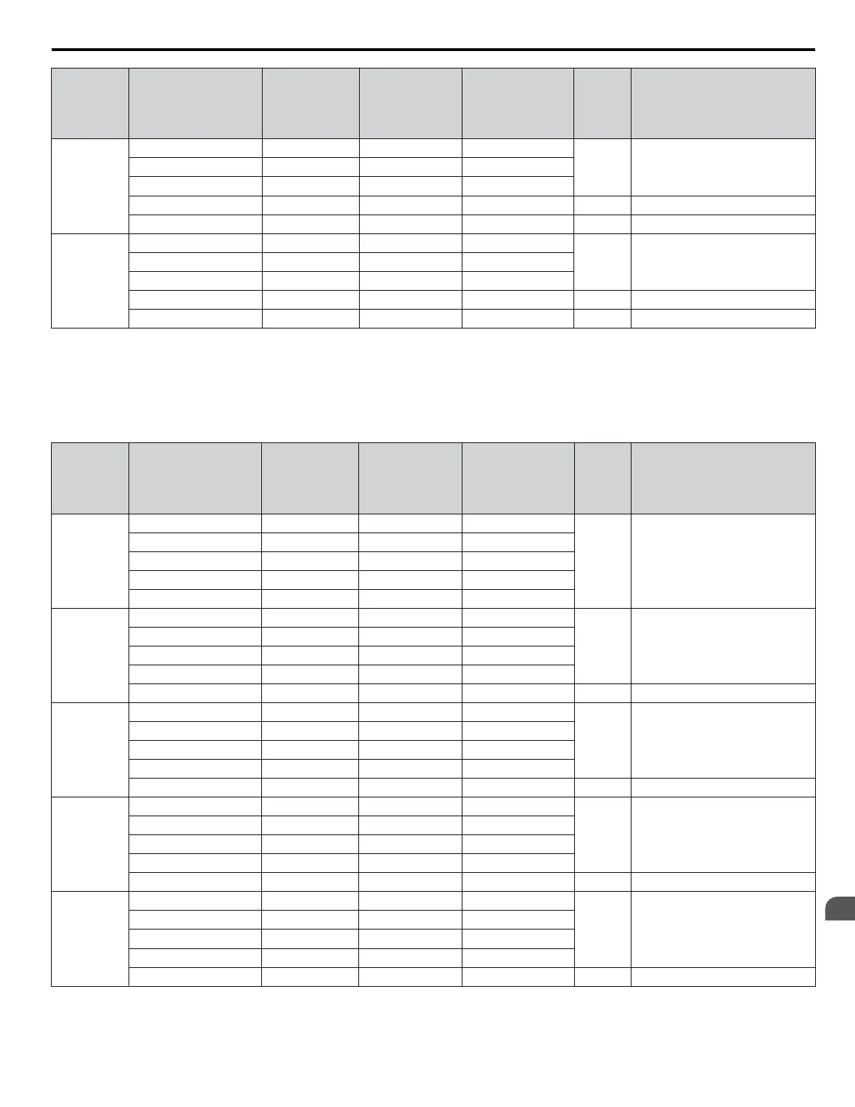
2o0360
R/L1, S/L2 2/0 X 2P 2/0 X 2P up to 250 kcmil
M12 32 to 40 (283 to 354)
U/T1, V/T2, W/T3 2/0 2/0 up to 250 kcmil
⊖, ⊕1
- - up to 250 kcmil
⊕3
- - up to 250 kcmil M10 18 to 23 (159 to 204)
GND 1 X 2P 1 X 2P up to 250 kcmil M12 32 to 40 (283 to 354)
2o0415
R/L1, S/L2 3/0 X 2P 3/0 X 2P up to 250 kcmil
M12 32 to 40 (283 to 354)
U/T1, V/T2, W/T3 3/0 3/0 up to 250 kcmil
⊖, ⊕1
- - up to 250 kcmil
⊕3
- - up to 250 kcmil M10 18 to 23 (159 to 204)
GND 1/0 X 2P 1/0 X 2P up to 250 kcmil M12 32 to 40 (283 to 354)
<1> Refer to local codes while selecting wire size for terminals ⊖, ⊕1, ⊕2 if these terminals need to be used for other optional power devices.
<2> The wire size recommended for terminal ⊖, ⊕1, ⊕2 is for DC type additional impedance only. See the additional impedance type recommended
in Table A.13 before choosing wire size for terminals ⊖, ⊕1, ⊕2.
<3> Terminal wire range is the range of wire sizes the terminals can accept. This information is intended to keep within the wire range of the terminals
while selecting a wire size for the terminals per local codes for the intended application of these terminals.
Table A.17 480 V Single-Phase Main Circuit Wiring and Tightening Torques
Drive Model Terminal
Recomm.
Gauge Without
Additional
Impedance
<1>
AWG, kcmil
Recomm.
Gauge With
Additional
Impedance
<2>
AWG, kcmil
Wire Range
AWG, kcmil
<3>
Screw
Size
Tightening Torque
N·m (lb.in.)
4o0002
4o0004
4o0005
4o0007
4o0009
4o0011
R/L1, S/L2 14 14 14 to 10
M4 1.2 to 1.5 (10.6 to 13.3)
U/T1, V/T2, W/T3 14 14 14 to 10
⊖, ⊕1, ⊕2
- 14 14 to 10
B1, B2 - - 14 to 10
GND 14 14 14 to 10
4o0018
R/L1, S/L2 12 12 12 to 6
M4 2.1 to 2.3 (18.6 to 20.4)
U/T1, V/T2, W/T3 12 12 12 to 6
⊖, ⊕1, ⊕2
- 12 12 to 6
B1, B2 - - 12 to 10
GND 12 12 12 to 10 M5 2.0 to 2.5 (17.7 to 221.1)
4o0023
R/L1, S/L2 12 12 12 to 6
M4 2.1 to 2.3 (18.6 to 20.4)
U/T1, V/T2, W/T3 12 12 12 to 6
⊖, ⊕1, ⊕2
- 12 12 to 6
B1, B2 - - 12 to 10
GND 12 12 12 to 10 M5 2.0 to 2.5 (17.7 to 221.1)
4o0031
R/L1, S/L2 8 10 10 to 6
M5 3.6 to 4.0 (31.8 to 35.4)
U/T1, V/T2, W/T3 10 10 10 to 6
⊖, ⊕1, ⊕2
- 10 10 to 6
B1, B2 - - 10 to 6
GND 8 10 10 to 8 M6 5.4 to 6.0 (47.8 to 53.1)
4o0038
R/L1, S/L2 8 8 10 to 6
M5 3.6 to 4.0 (31.8 to 35.4)
U/T1, V/T2, W/T3 10 10 10 to 6
⊖, ⊕1, ⊕2
- 10 10 to 6
B1, B2 - - 10 to 6
GND 8 8 10 to 6 M6 5.4 to 6.0 (47.8 to 53.1)
A.4 Drive Derating Data
YASKAWA SIEP YAIP1U 01C AC Drive - P1000 Technical Manual
411
A
Specifications

 Loading...


