Def / Type
FbEq 16b / 32b
DescriptionName / Range /
Selection
No.
- / real32Defines the droop rate in percent of the nominal motor
speed.
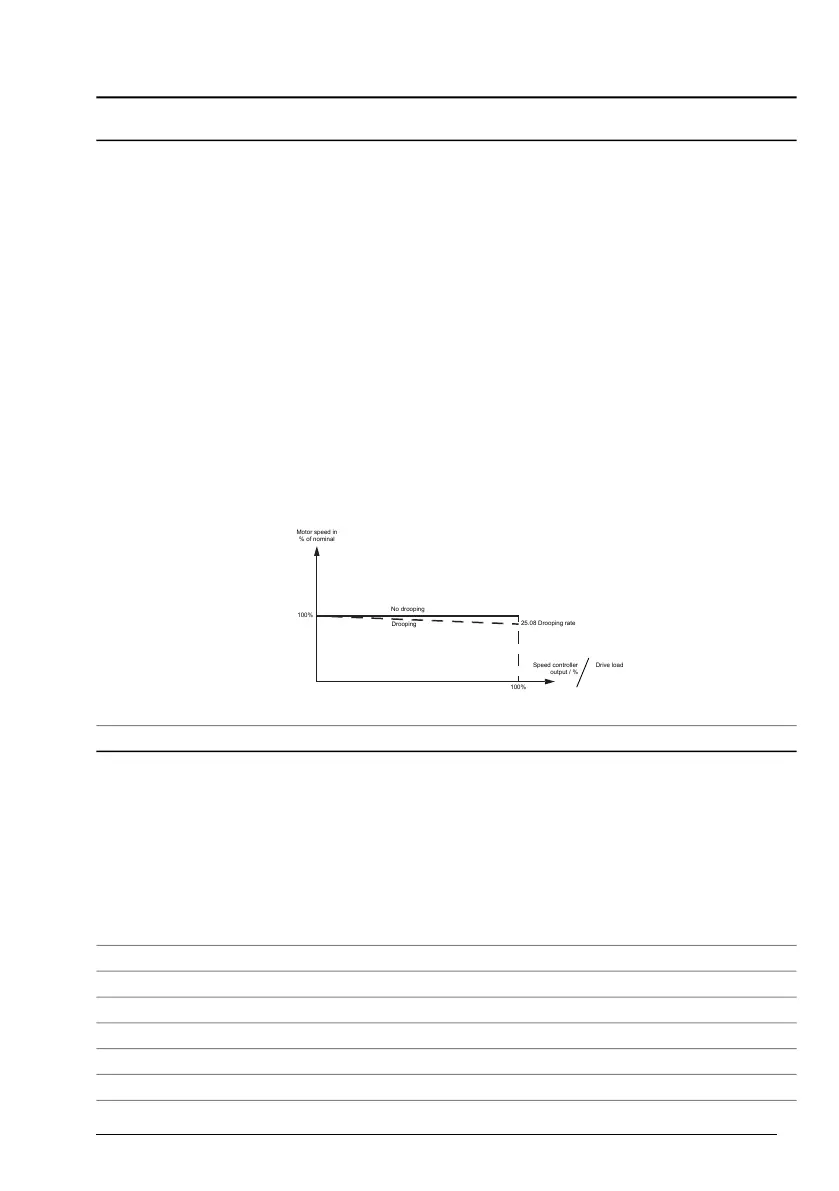
Drooping decreases the drive speed slightly as the drive
load increases. The actual speed decrease at a certain
operating point depends on the droop rate setting and the
drive load (= torque reference / speed controller output).
At 100 % speed controller output, drooping is at its nominal
level, i.e. equal to the value of this parameter. The drooping
effect decreases linearly to zero along with the decreasing
load.
The droop rate can be used e.g. to adjust the load sharing
in a Master/Follower application run by several drives. In
a Master/Follower application the motor shafts are coupled
to each other.
The correct droop rate for a process must be found out
case by case in practice.
Speed decrease = Speed controller output × Drooping ×
Nominal speed
Example: Speed controller output is 50 %, droop rate is
1 %, nominal speed of the drive is 1500 rpm.
Speed decrease = 0.50 × 0.01 × 1500 rpm = 7.5 rpm.
Motor speed in
% of nominal
Speed controller
output / %
Drive load
100%
No drooping
Drooping
100%
25.08 Drooping rate
Drooping rate25.8
100 = 1 % / 100 = 1 %Droop rate.0.00 ... 100.00 %
Not selected / uint32Selects the source for enabling/disabling speed controller
output balancing.
This function is used to generate a smooth, “bumpless”
transfer from a torque- or tension-controlled motor back to
being speed-controlled. When balancing is enabled, the
output of the speed controller is forced to the value of 25.10
Speed ctrl balancing ref.
Balancing is also possible in the ramp generator (see
parameter 23.26 Ramp out balancing enable).
0 = Disabled
1 = Enabled
Speed ctrl balancing
enable
25.9
00Not selected
11Selected
2
Digital input DI1 (10.2 DI delayed status, bit 0).
DI1
3
Digital input DI2 (10.2 DI delayed status, bit 1).
DI2
4
Digital input DI3 (10.2 DI delayed status, bit 2).
DI3
5
Digital input DI4 (10.2 DI delayed status, bit 3).
DI4
Parameters 289


 To Next Page