Working with contacts
and relays
147
1SVC 440 795 M1100
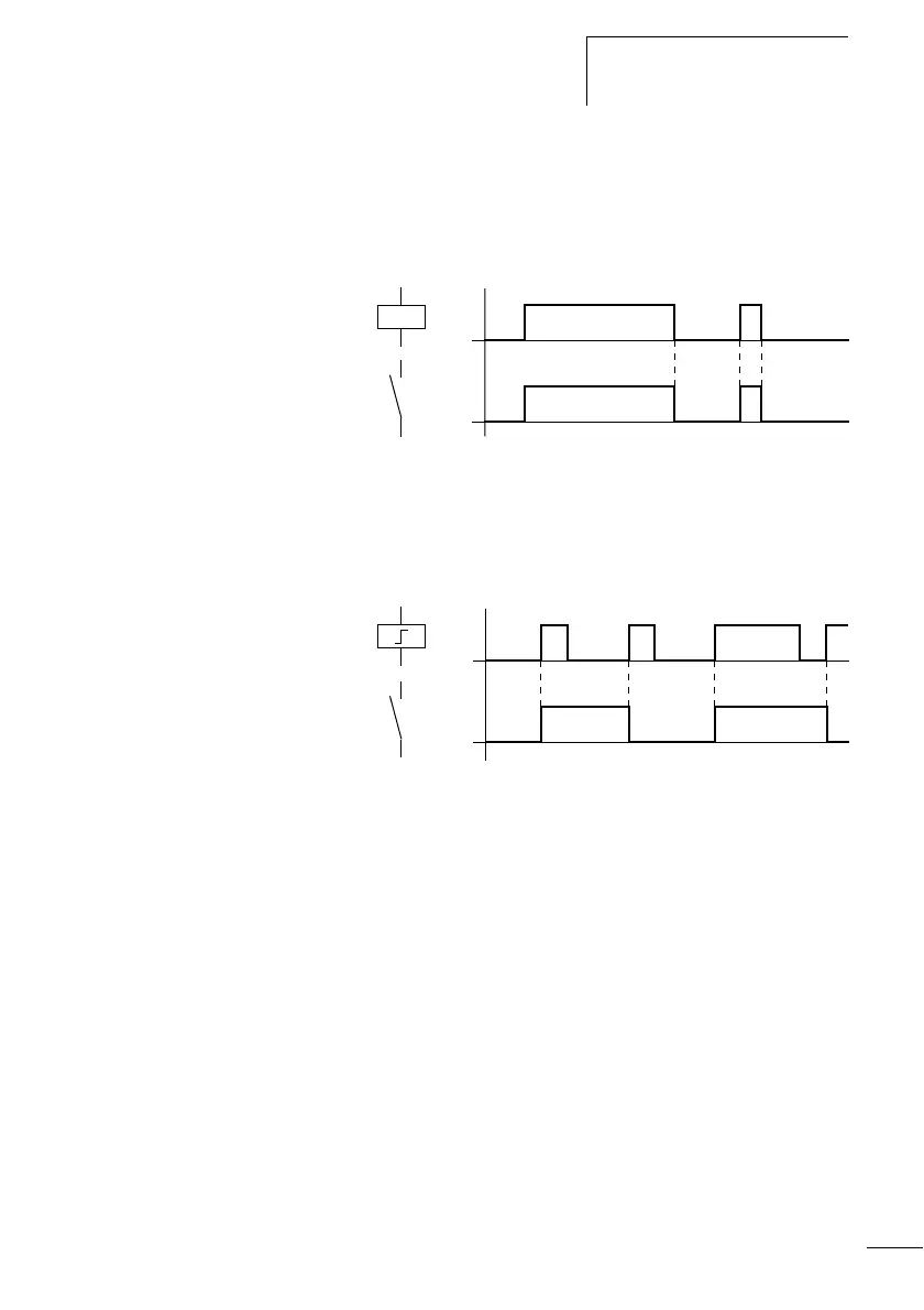
Coil with contactor function Ä
The output signal follows immediately after the input signal
and the relay acts as a contactor.
Figure: 88: Signal diagram of contactor function
Impulse relay ä
The relay coil switches with every change of the input signal
from 0 to 1. The relay behaves like a bistable flip-flop.
:
Figure: 89: Signal diagram of impulse relay
A coil is automatically switched off if the power fails and if
STOP mode is active. Exception: Retentive coils retain
signal 1 (see a section “Retention”, page 363).
Set
S and Reset R coil function
The Set
S and Reset R coil functions are normally used in
pairs.
The relay picks up when the coil is set (A) and remains in this
state until it is reset (B) by the coil function.
The supply voltage is switched off (C), the coil does not have
a retentive effect.
on
on
on
on