Wiring with the display system
148
1SVC 440 795 M1100
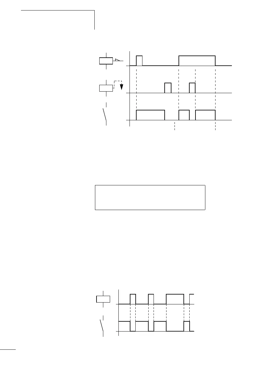
Figure: 90: Signal diagram of Set and Reset
If both coils are triggered at the same time, priority is given
to the coil in the circuit diagram with the higher rung
number. This is shown in the above signal diagram in
section B.
Figure: 91: Simultaneous triggering of Q 01
In the example above, the reset coil has priority with
simultaneous triggering of the set and reset coils.
Coil negation (inverse contactor function)
Å
The output signal is simply an inversion of the input signal;
the relay operates like a contactor with contacts that have
been negated. If the coil is triggered with the state 1, the coil
switches its N/O contacts to the state 0.
Figure: 92: Signal diagram of inverse contactor function
on
on
S
R
on
AB C
I 05---------------------------S Q 01
I 10---------------------------R Q 01
on
on