Wiring with the display system
206
1SVC 440 795 M1100
Parameter display and parameter set for PID
controller:
In the parameter display of a PID controller you set the operating
mode, the setpoints and enable the parameter display.
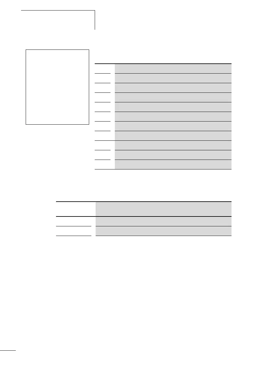
Operating modes of the PID controller
Z
Inputs
The function block inputs
>I1, >I2, >KP, >TN,
>TV, >TC
and >MV can have the following operands:
•Constants
• Markers MD, MW, MB
• Analog inputs IA01 to IA04
– IA01: Terminal I7
– IA02: Terminal I8
– IA03: Terminal I11
– IA04: Terminal I12
• Analog output QA01
• Actual value …QV> of another function block
DC02 UNP +
>I1
>I2
>KP
>TN
>TV
>TC
>MV
QV>
DC02 PID controller function block number 02
UNP Unipolar mode
+ Appears in the parameter display
>I1 Setpoint of PID controller
>I2 Actual value of PID controller
>KP Proportional gain K
p
>TN Reset time T
n
>TV Rate time T
v
>TC Scan time
>MV Manual manipulated variable
QV> Manipulated variable
Parameter Manipulated variable is output as
UNP Unipolar 12-bit value 0 to +4095
BIP Bipolar 13-bit value (signed 12-bit value) –4096 to +4095
 Loading...


