Wiring with the display system
256
1SVC 440 795 M1100
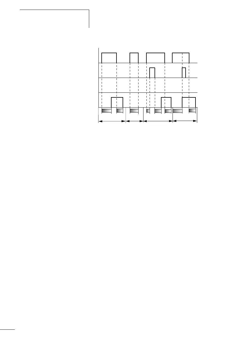
Figure: 135: Signal diagram timing relay, on- and off-delayed 1
1: Trigger coil T…EN
2: Stop coil T…ST
3: Reset coil T…RE
4: Switching contact (N/O contact) T…Q1
t
s1
: Pick-up time
t
s2
: Drop-out time
•Range A:
The relay processes the two times without any interruption.
•Range B:
The trigger coil drops out before the on-delay is reached.
•Range C:
The stop coil stops the timeout of the on-delay.
•Range D:
The stop coil has no effect in this range.
A
B
C
1
2
4
3
D
tt
s1
t
s2
t
s2
t
s1
t
s2
t
1
+ t
2
= t
s1