EasyManuals Logo

ABB CL Series User Manual

ABB CL Series
428 pages
To Next Page IconTo Next Page
To Previous Page IconTo Previous Page
Page #260 background imageLoading...
Page #260 background image
Function blocks
257
1SVC 440 795 M1100
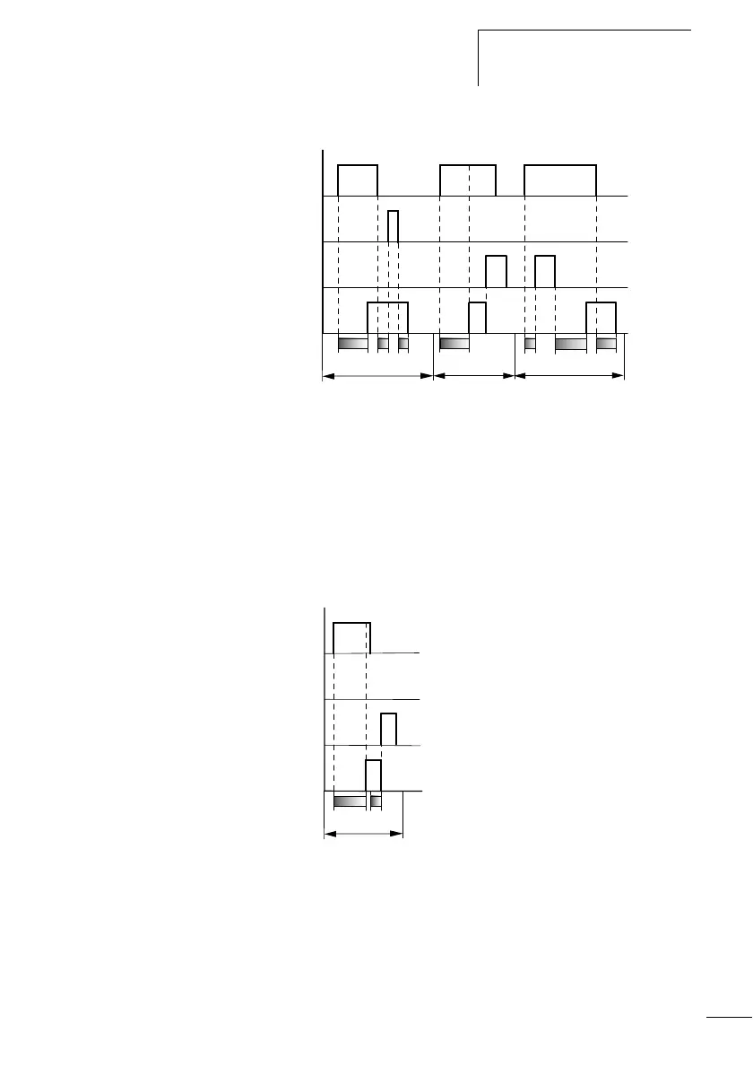
Figure: 136: Signal diagram timing relay, on- and off-delayed 2
Range E:
The stop coil stops the timeout of the off-delay.
•Range F:
The reset coil resets the relay after the on-delay has elapsed
•Range G:
The reset coil resets the relay and the contact whilst the on-delay
is timing out. After the reset coil drops out, the time elapses
normally.
Figure: 137: Signal diagram timing relay, on- and off-delayed 3
•Range H:
The reset signal interrupts the timing out of the set time.
E
F
t
1
+ t
2
= t
s2
G
1
2
4
3
tt
s1
t
s1
t
s1
t
s2
H
t
1
2
4
3
t
s1

Table of Contents

Questions and Answers:

Question and Answer IconNeed help?

Do you have a question about the ABB CL Series and is the answer not in the manual?

ABB CL Series Specifications

General IconGeneral
ManufacturerABB
Rated Control Supply Voltage (Us)24 V DC
MountingDIN Rail
CategoryRelays
Contact ConfigurationSPDT
Coil Voltage24 V DC
Operating Temperature-40°C to +70°C
Electrical Life100 Thousand Cycles
OutputRelay

Related product manuals