Wiring with the display system
258
1SVC 440 795 M1100
Timing relay, single pulse
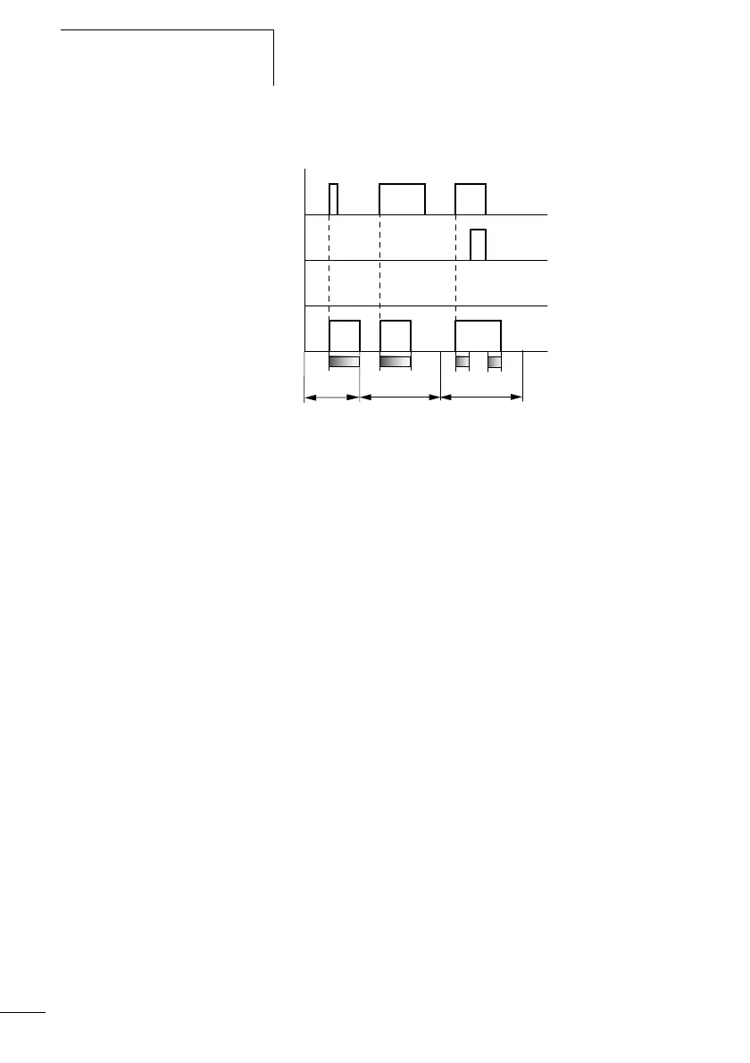
Figure: 138: Signal diagram timing relay, pulse shaping 1
1: Trigger coil T…EN
2: Stop coil T…ST
3: Reset coil T…RE
4: Switching contact (N/O contact) T…Q1
•Range A:
The trigger signal is short and is lengthened
•Range B:
The Trigger signal is longer than the set time.
•Range C:
The stop coil interrupts the timing out of the set time.
A B
t
1
+ t
2
= t
s
t
s
t
s
C
1
2
4
3