EasyManuals Logo

ABB CL Series User Manual

ABB CL Series
428 pages
To Next Page IconTo Next Page
To Previous Page IconTo Previous Page
Page #262 background imageLoading...
Page #262 background image
Function blocks
259
1SVC 440 795 M1100
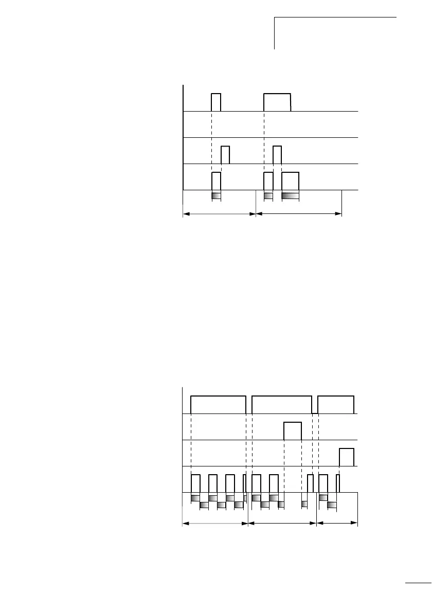
Figure: 139: Operational diagram timing relay, pulse shaping 2
•Range D:
The reset coil resets the timing relay.
Range E: The reset coil resets the timing relay. The trigger coil is
still activated after the reset coil has been deactivated and the
time is still running.
Timing relay, synchronous and asynchronous flashing
Time value >I1: Mark time
Time value >I2: Space time
Synchronous (symmetrical) flashing: >I1 equal >I2
Asynchronous flashing: >I1 not equal >I2
Figure: 140: Operational diagram: Timing relay, synchronous
and asynchronous flashing
t
D
E
t t
s
1
2
4
3
t
1
+ t
2
= t
s2
t
s1
t
s1
t
s1
t
s2
t
s2
t
s1
t
s1
t
s2
t
s2
AB
1
2
4
3
t
t
s1
t
s2
C

Table of Contents

Questions and Answers:

Question and Answer IconNeed help?

Do you have a question about the ABB CL Series and is the answer not in the manual?

ABB CL Series Specifications

General IconGeneral
ManufacturerABB
Rated Control Supply Voltage (Us)24 V DC
MountingDIN Rail
CategoryRelays
Contact ConfigurationSPDT
Coil Voltage24 V DC
Operating Temperature-40°C to +70°C
Electrical Life100 Thousand Cycles
OutputRelay

Related product manuals