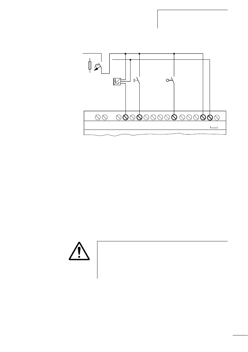
Connecting inputs
57
1SVC 440 795 M1100
Figure: 40: CL-LER.18DC2, CL-LET.20DC2
Connecting analog inputs
Inputs I7, I8, I11 and I12 can also be used to connect analog
voltages ranging from 0 V to 10 V.
The following applies:
•I7 = IA01
•I8 = IA02
• I11 = IA03
• I12 = IA04
The resolution is 10 bits = 0 to 1023.
X Use shielded twisted pair cables to prevent interference
with the analog signals.
X With short cable lengths, ground the shield at both ends
using a large contact area. If the cable length is more than
around 30 m, grounding at both ends can result in
equalisation currents between the two grounding points
L01 +
L01 –
R10R9R8R7R6R5R4R3R2R1E+ E–
R11
R12 0V0V+24V
24 V H
F1
Caution!
Analog signals are more sensitive to interference than digital
signals. Consequently, greater care must be taken when
laying and connecting the signal lines. Incorrect switching
states may occur if they are not connected correctly.