Installation
58
1SVC 440 795 M1100
and thus in the interference of analog signals. In this case,
only ground the cable at one end.
X Do not lay signal cables parallel to power cables.
X Connect inductive loads to be switched via the display
system outputs to a separate power feed, or use a
suppressor circuit for motors and valves. If loads such as
motors, solenoid valves or contactors are operated with
display system via the same power feed, switching may
result in interference on the analog input signals.
The following circuits contain examples of applications for
analog value processing.
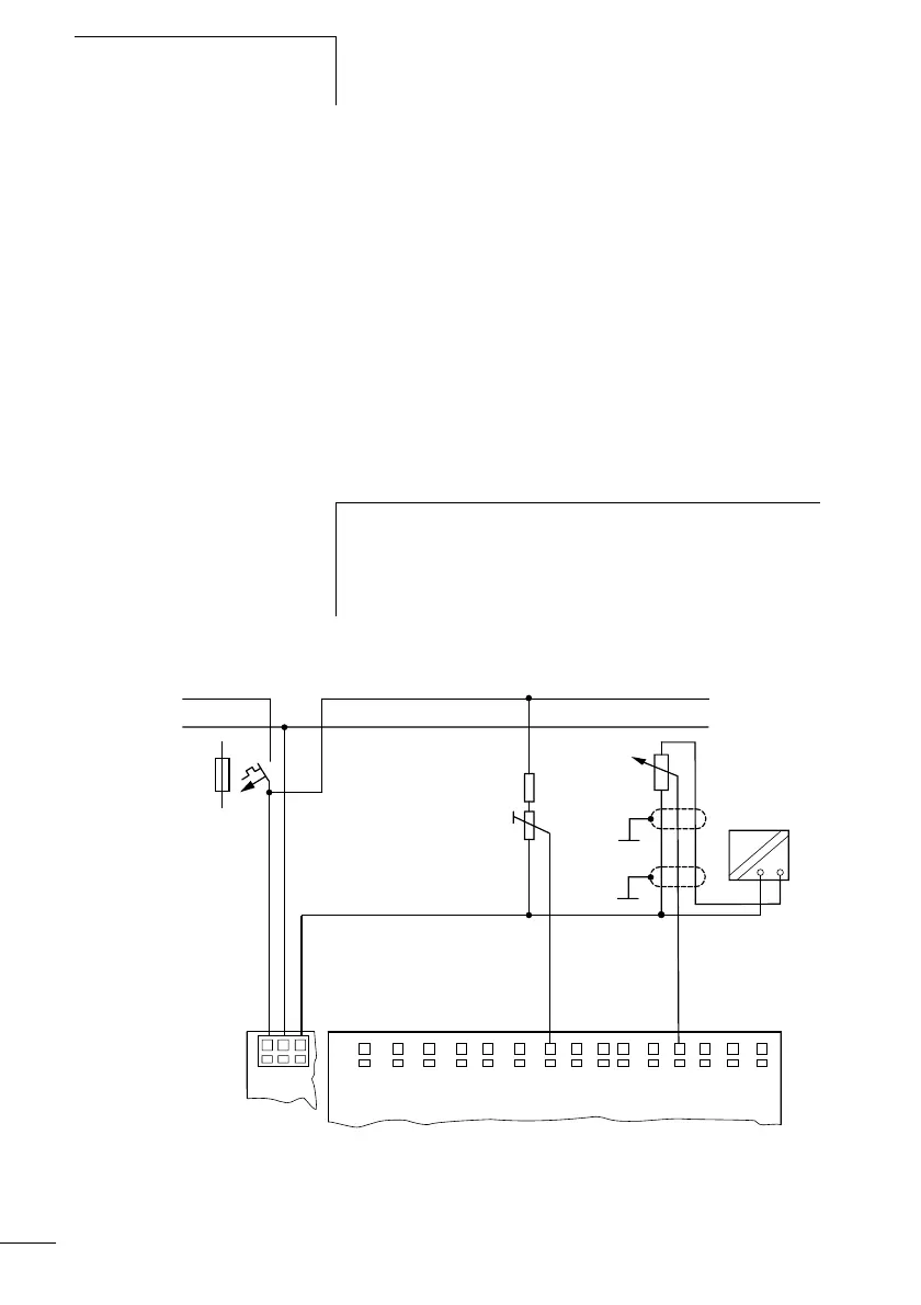
Setpoint potentiometer
Figure: 41: Setpoint potentiometer with upstream resistor
Use a potentiometer with a resistance of F 1 kO, e.g. 1 kO,
0.25 W.
h
Ensure that the reference potential is galvanically
connected. Connect the 0 V of the power supply unit for the
setpoint potentiometers and various sensors shown in the
examples with the 0 V of the display system power supply.
L01–
> 1 A
L01+
I1 I3 I4 I7 I8 I9 I10
L02+
I2 I5 I6 I11
I12
0 V
+12 V
H
h
1.3 kO/0.25 W
1 kO/0.25 W
+24V 0V 0V
 Loading...


