1-18 Agilent 4155B/4156B User’s Guide Vol.2, Edition 5
Measurement Units
Voltage Monitor Unit (VMU)
Table 1-13 VMU Voltage Ranges and Resolutions
When you perform knob sweep measurement,
• only 20 V range is available for grounded measurement mode
• only 2 V range is available for differential measurement mode
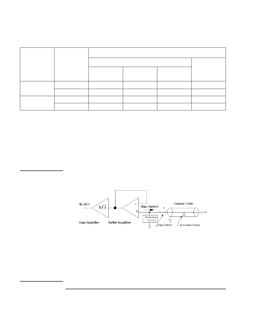
NOTE Bias Current of Buffer Amplifier may Damage DUT
The following figure shows a circuit diagram of a VMU.
When a coaxial cable is connected to VMU and when the measurement terminal of
VMU is open, the charge of the bias buffer amplifier current in the VMU increases
the measurement terminal voltage.
After a long time charge, connecting DUT to the measurement terminal may
damage the DUT by the discharging.
For the details of how to prevent this damage, refer to “If Measurement Damages
the Device under Test” in Chapter 8.
Measurement
Mode
Range
Measurement Resolutions
a
a. Measurement resolution depends on the integration time setting. For Knob sweep measurement, see 20 V
Range (for Grounded mode) and 2 V Range (for Differential mode) of Integration Time 80 ms to 560 ms.
Integration Time
High Speed
Sampling
Measurement
b
b. This column is applied to the sampling measurement that initial interval is set to 480 ms or shorter.
1PLC or
Longer
640 ms to 1.92
ms
80 ms to 560 ms
Grounded
Measurement
2 V
2 mV
20 mV200 mV2 mV
20 V 20 mV200 mV 2 mV 20 mV
Differential
Measurement
0.2 V 1 mV2 mV20 mV200 mV
2 V 2 mV20 mV200 mV2 mV