1-20 Agilent 4155B/4156B User’s Guide Vol.2, Edition 5
Measurement Units
Pulse Generator Unit (PGU)
Pulse Generator Unit (PGU)
Two pulse generator units (PGUs) are available, which are in the 41501A/B (SMU
and pulse generator expander). Each PGU provides a pulsed output, and can also
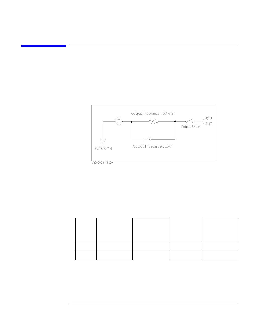
function as a dc source. For pulsed output of PGU, you can select 50 W or Low
impedance. Figure 1-8 shows simplified PGU circuit diagram.
Figure 1-8 Simplified PGU Circuit Diagram
The PGU output value is defined to be the value that is output if the PGU output
terminal is open. So, when a load is connected and PGU impedance is set to 50 W,
the actual output value will be different. For example, if connected load is 50 W,
specified PGU output impedance is 50 W, and specified output value is 2 V, the PGU
outputs 1 V.
Table 1-14 shows the PGU setting ranges and resolutions.
Table 1-14 PGU Setting Ranges and Resolutions
Range
Peak Setting
Value
a
a. Maximum peak-to-peak voltage is 40 V.
Base Setting
Value
Resolution
Maximum
Current
b
b. If pulse width £ 1 ms, pulse duty is £ 50 %, and average current output is £
±100 mA, the peak current output can be up to ±200 mA.
20 V 0 £ ½V½ £ 20 V 0 £ ½V½ £ 20 V 4 mV ±100 mA
40 V 0 £ ½V½ £ 40 V 0 £ ½V½ £ 40 V 8 mV ±100 mA