Home
Agilent Technologies
Measuring Instruments
8163B
Agilent Technologies 8163B User Manual
5
of 1
of 1 rating
466 pages
Give review
Manual
Specs
To Next Page
To Next Page
To Previous Page
To Previous Page
Loading...
Co
m
p
a
c
t
T
u
n
a
b
l
e La
s
e
r
s
H
o
w
t
o
U
s
e
a c
o
m
p
act
T
u
n
a
b
l
e
L
a
se
r
16
2
A
g
i
l
e
n
t
816
3A
/
B
,
8
164A
/
B
&
816
6A
/
B
Mai
n
fr
ame
s
, Si
x
t
h
E
d
i
t
i
o
n
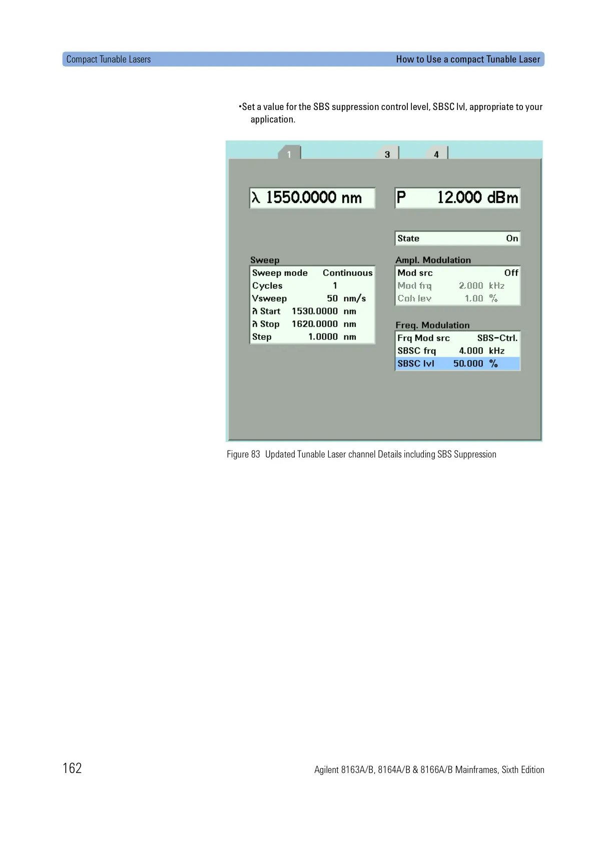
•
S
e
t
a
v
a
l
u
e
f
o
r
t
h
e
S
B
S
s
u
p
p
r
e
s
s
i
o
n
c
o
n
t
r
o
l
l
e
v
e
l
,
S
B
S
C
l
v
l
,
a
p
p
r
o
p
r
i
a
t
e
t
o
y
o
u
r
a
ppl
i
c
a
t
i
o
n
.
F
i
gu
r
e
83
U
p
da
te
d T
u
n
a
bl
e
L
a
se
r
c
h
a
n
n
e
l
D
e
t
a
i
l
s i
n
c
l
u
d
i
n
g S
B
S
S
u
pp
r
e
ss
i
o
n
All manuals and user guides at all-guides.com
161
163
Table of Contents
Table of Contents
5
Getting Started
23
Safety Considerations
25
General
26
Operating Environment
26
Line Power Requirements
27
Input/Output Signals
27
Line Power Connectors
28
Instrument Markings
29
Laser Safety Information
30
Table 1 Standard Laser Source Modules - Laser Safety Information
30
Table 2 High Power Laser Source Modules - Laser Safety Information
30
Table 3 DFB Laser Source Modules - Laser Safety Information
31
Table 4 Backloadable Tunable Laser Modules - Laser Safety Information
32
Table 5 Backloadable Tunable Laser Modules (Discontinued)
32
Table 6 Compact Tunable Laser Modules - Laser Safety Information
33
Table 7 Compact Tunable Laser Modules (Discontinued)
33
Laser Safety Labels
34
Figure 1 Class 1 Safety Label
34
Table 8 Return Loss Modules - Laser Safety Information
34
Figure 2 Class 1M Safety Label - Agilent 81655A/6A/7A, 81662A/3A
35
Agilent 8163A/B Lightwave Multimeter
36
Figure 3 the Agilent 8163B Lightwave Multimeter Mainframe
36
Agilent 8164A/B Lightwave Measurement System
37
Figure 4 the Agilent 8164B Lightwave Measurement System Mainframe
37
Agilent 8166A/B Lightwave Multichannel System
38
Figure 5 the Agilent 8166A/B Lightwave Multichannel System Mainframe
38
A Description of the User Interface
39
Figure 6 the Agilent 8164A/B Lightwave Measurement System User
39
Password
40
Figure 7 the Agilent 8163A/B Lightwave Multimeter User Interface
40
User Interface Features
41
How to Navigate/Modify the Display
43
Figure 8 the Agilent 8163B's Overview Screen
43
Figure 9 the Agilent 8164A/B's Overview Screen
44
Figure 10 the Agilent 8166A Overview Screen
44
Figure 13 the Agilent 8163B's Details Screen for a Power Sensor Channel
46
Figure 14 the Agilent 8164A/B's Details Sreen for a Tunable Laser Channel
47
Figure 15 the Agilent 8166A Details Screen for a Power Sensor Channel
47
Figure 16 the Agilent 8163B/6B Menu for a Power Sensor Channel
48
Figure 17 the Agilent 8164A/B Menu for Power Sensor Channel
48
Figure 18 the Agilent 8163B System Configuration Menu
49
Figure 19 the Agilent 8164A/B System Configuration Menu
49
Figure 20 the Agilent 8164A/B Help Screen
50
Figure 21 the Agilent 8164A/B Help Index
50
Figure 22 the Applications Menu
51
How to Change the Value of a Parameter
53
How to Select a Parameter
53
How to Accept the New Value of a Parameter
54
How to Make a Big Change to a Continuous Parameter
54
How to Make a Small Change to a Continuous Parameter
55
Figure 23 the First Digit before the Decimal Point Is Highlighted First
55
How to Change a Discrete Parameter
57
How to Set All Parameters to Their Default Values
58
If You Make a Mistake
58
If the Parameter Changes to Different Value
58
A Sample Session
59
How to Measure the Power of a Modulated Signal
60
Figure 25 Connecting the Instrument for the Sample Session
60
Additional Information
63
Using the System Utilities
64
Figure 26 the Agilent 8163B/6B Configuration Menu
64
Figure 27 the Agilent 8164A/B System Configuration Menu
64
How to Set the Backlight
65
Figure 28 Entering a Backlight Value
65
How to Set the Date & Time
66
Figure 29 Editing the Date and the Time
67
How to Lock/Unlock the High-Power Laser Sources
68
Figure 30 Unlocking the Instument
68
How to Set the Trigger Configuration
69
Figure 31 Changing the Triggering Mode
69
How to Configure Startup Applications
70
How to Configure Your Foot Pedal
71
Figure 32 Enabling/Disabling the Foot Panel
71
How to Set the GPIB Address
72
How to Set the Speed of the Serial Interface
73
Figure 34 Selecting a Baudrate for the Serial Interface
73
How to Update a Module
74
How to Select the Printer Type
75
How to Change the Password
76
If You Forget Your Password
76
How to Get Information about Modules
77
Figure 37 Slots with Installed Modules
77
Figure 38 Viewing Information about a Module
78
How to Get Information about the Mainframe
79
Figure 39 Viewing Information about the Mainframe
79
How to Connect an External Monitor
80
Figure 40 Rear Panel of the Agilent 8164B Lightwave Measurement System
80
How to Connect a Printer
81
Power Measurement
83
How to Measure Power
84
The Power Value
84
Figure 41 the Number of Digits Menu
84
How to Set the Power Unit
85
Figure 42 Selecting the Power Unit
86
How to Set the Calibration Offset
87
How to Set the Reference Level
88
Figure 43 Referencing Another Channel
90
How to Set the Wavelength
91
How to Remove Electrical Offsets
91
Figure 44 Module Channels that Are Setting
92
Figure 46 Zeroing Fails, if the Power Meter Receives Input Light
93
How to Choose the Range Mode
94
How to Set the Range
95
Figure 48 Manual Range Mode - Within Range
96
Figure 49 out of Range - Power Greater than Upper Power Limit
97
Figure 50 out of Range - Power Less than Resolution
97
Table 9 Upper Power Limits and Resolution for Various Power Ranges
99
How to Set the Averaging Time
100
Figure 52 Measurement with Tavg ~1 Second
100
How to Choose the Minmax Mode
101
Figure 53 the Window and Refresh Modes
102
Figure 54 Minmax Mode Screen
102
How to Turn off Minmax Mode
103
How to Hold the Screen
103
Figure 55 Power Module Channel Is Held - Overview Screen
103
How to Use Triggers
104
Dual Power Meters - Master and Slave Channels
107
Table 10 Parameters that Can Only be Set Using the Master Channel
107
Laser Sources
109
How to Use Laser Source Modules
110
The Laser Wavelength Value
110
Figure 58 Menu of Parameters for a Fixed Wavelength Laser Source
110
How to Enable/Disable Laser Output
111
Figure 59 Dual-Wavelength Laser Source Outputs both Wavelength
111
How to Set Attenuation
112
Figure 60 the Power Sensor Details Screen
112
How to Modulate the Optical Output
113
How to Use the Internal Modulation
114
Figure 61 the Modulated Signal
114
How to Use Triggers
117
Tunable Lasers
119
What Is a Tunable Laser
121
How to Set the Power
121
How to Set the Output Power of a CW Signal
122
Figure 63 Setting Hogh Power Parameters
123
Figure 64 Setting Low SSE Parameter
123
Figure 65 Setting Attenuation
125
What Is Excessive Power
126
How to Set the Laser to the Dark Position
127
The Analog Output
128
Figure 67 Output Power and the Analog Output in <Manual ATT.> Mode
128
How to Set the Wavelength
130
Wavelength Range
130
Figure 68 Specified and Permitted Wavelength Range
130
How to Set the Wavelength Directly
131
How to Set a Relative Wavelength
132
Figure 69 Setting a Relative Wavelength
132
How to Perform a Wavelength Sweep
134
What Is a Wavelength Sweep
134
How to Set the Wavelength Sweep
135
Figure 70 the Parameters for a Stepped Wavelength Sweep
135
How to Perform a Sweep
137
Figure 72 Executing a Stepped Sweep
138
Figure 73 Pausing a Stepped Sweep
138
Figure 74 Performing a Manual Sweep
141
How to Modulate a Signal
142
How to Use the Internal Modulation
142
Figure 75 the Modulated Signal
142
How to Use External Modulation
144
Figure 76 External Digital Modulation
144
Figure 77 External Analog Modulation and Output Powr
145
Figure 78 Wavelength Locking
146
How to Configure the Modulation Output
149
How to Use Triggers
150
How to Use Input Triggering
150
How to Use Output Triggering
152
How to Use Auxiliary Functions
153
Automatic Realignment
153
How to Perform a Lambda Zero
155
Auto Cal off
156
Compact Tunable Lasers
159
Compact Tunable Laser Modules
160
Table 11 the Agilent Compact TLS Family
160
How to Use a Compact Tunable Laser
161
The User Interface
161
SBS Suppression
161
Figure 83 Updated Tunable Laser Channel Details Including SBS
162
Return Loss Measurement
163
Getting Started with Return Loss
165
What Is Return Loss
165
What Is Insertion Loss
165
Equipment Required
166
Figure 84 Measuring Return Loss and Insertion Loss
166
How to Choose a Light Source
167
Return Loss Modules
168
Figure 85 the Contents of the Agilent 81610A Return Loss Module
168
Figure 86 the Contents of the Agilent 81611A and Agilent 81612A Return
168
Figure 87 the Contents of the Agilent 81613A Return Loss Modules
169
Calibration Measurements
170
Return Loss Measurement
171
Table 12 High Return-Loss Patchcords
171
Setup
172
Figure 88 Return Loss Measurement Setup - External Source Used
172
Figure 89 Return Loss Measurement Setup - Internal Source Used
172
Figure 90 Agilent 8161X Details Screen
173
Figure 91 Reflectance Calibration Using RL Reference
175
Figure 92 Termination Calibration
175
Calibrating the Return Loss Module
176
Calibration Using the Agilent 81000BR Reference Reflector
177
Figure 93 Reflectance Calibration - External Source
177
Figure 94 Reflection Calibration - Internal Source
177
Figure 95 Measuring the Reflection Reference
178
Figure 96 Termination Calibration - External Source
179
Figure 97 Termination Calibration - Internal Source
179
Calibration Using the Agilent 81610CC Reference Cable
180
Figure 98 Measuring the Return Loss of the Reference Cable
180
Figure 99 Measuring the Return Loss of the Reference Cable
180
Figure 100 Power Transmitted through the Reference Cable
181
Figure 101 Power Transmitted through the Reference Cable
181
Figure 102 Power Transmitted through the Measurement Patchcord
182
Figure 103 Power Transmitted through the Measurement Patchcord
182
Figure 104 Measuring the Termination Parameter - External Source
183
Figure 105 Measuring the Termination Parameter - Internal Source
183
How to Measure Return Loss
184
Figure 106 Measuring the Return Loss of the DUT
184
Figure 107 Measuring the Power Transmitted through the DUT
184
Viewing the Calibration Values
186
Figure 108 the Calibration Parameters Screens - Return Loss Diode
186
Figure 109 the Calibration Parameters Screens - Monitor Diode
187
Figure 110 the Calibration Parameters Screens - User Data
188
A Background to Return Loss Measurement
189
Measuring the Reflected Power from a Component with Known Reflection Factor
189
Figure 111 Measuring the Power from a Component with a Known
189
Measuring the Power Transmitted through the Reflection Reference
190
Measuring the Power When There Are no Reflections
190
Figure 112 Measuring the Power Transmitted through the Reflection
190
Figure 113 Measuring the Power with the Connector Terminated
190
Reference
190
Measuring the Power Transmitted through the Measurement Patchcord
191
Measuring the Reflections from the DUT
191
Figure 114 Measuring the Power Transmitted through the Measurement
191
Figure 115 Measuring the Reflections from the Device under Test
191
Patchcord
191
Measuring the Power Transmitted through the DUT
192
Calculating the Return Loss of the DUT
192
Figure 116 Measuring the Power Transmitted through the Device under Test
192
Calculating the Front Panel Delta
195
Figure 117 Generalization of a Return Loss Measurement
195
Calculating the Insertion Loss of the DUT
196
Setting Attenuation And/Or Power Levels
197
Agilent 8157Xa Variable Optical Attenuator Modules
198
Figure 118 81576A/77A Attenuator Module Power Control Loop
198
Table 13 the Agilent 8157Xa Variable Optical Attenuator Family
198
How to Use a Variable Optical Attenuator Module
199
The User Interface
199
Figure 119 81570A/71A/73A Attenuator Module, 8164A/B GUI Overview
199
Figure 120 81570A/71A/73A Attenuator Module, 8164A/B GUI Details
200
How to Control the Shutter
202
How to Set Attenuation
203
Figure 121 Attenuation Factor Set to 4.000 Db
203
Figure 122 81570A/71A/73A - Attenuation Factor Applied with no Offset
205
Figure 123 81570A/71A/73A Attenuation Offset
205
How to Set a Power Level
207
Figure 124 81576A/77A Setting P
211
How to Compensate for Wavelength Dependencies in Your Test Setup
212
How to Compensate for Wavelength Dependencies in
212
Your Test Setup
212
Figure 125 the Λ Offset Table
213
Figure 126 Extrapolation and Interpolation of Offset Values
215
How to Use the Power Control Feature
216
Attenuator Menu Options
217
Figure 127 81570A/71A/73A Attenuator Menu Options
217
Figure 128 81576A/77A Attenuator Menu Options
217
Attenuator Status Indicators
218
Table 14 Attenuator Status Indicators
218
Switching Optical Routes
219
Agilent 8159Xb Optical Switch Modules
220
Figure 129 Agilent 81594B Optical Switch Module
220
Table 15 the Agilent 8159Xb Optical Switch Family
220
How to Use an Optical Switch Module
221
The User Interface
221
Figure 130 Optical Switch Module, User Interface Overview Display
221
Figure 131 Optical Switch Module, 8164A/B User Interface Details
222
Dependent and Independent Routing
223
How to Set Route a
224
How to Set Route B
224
How to Toggle the Switch Path
225
Typical Applications
226
Selecting a Laser Source
226
Figure 132 Laser Source Selection
226
Selecting Measurement and Calibration Paths
227
Inserting or Bypassing an Optical Component
227
Figure 133 Measurement Path Selection
227
Figure 134 Circuit Selection with Crossover Switch
227
Selecting One of Several Duts in a Parallel Test Setup
228
Selecting One of Several Instruments
228
Figure 135 DUT Selection in a Parallel Test Setup
228
Figure 136 Test Instruments Selection
228
Applications
229
Working with Application Graphs
231
Figure 137 the Application Graph
231
How to Set Markers
233
How to Zoom in
233
How to Zoom out
234
To Switch the Grid On/Off
234
How to Use Legends
235
Figure 138 the Graph Legend Screen
236
How to Select the Samples Display
237
Figure 139 Samples Display - <Line
237
Figure 140 Samples Display - <Samples
238
Figure 141 Samples Display - <Samples & Line
238
How to Read Curve Values
239
Figure 142 the Lock to Curve Menu
239
Figure 143 Lock to Samples on
240
Figure 144 Lock the Samples off
241
The Logging Application
242
Figure 145 Example Logging Application
242
How to Set up a Logging Function
243
Figure 146 the Applications Menu
243
Figure 147 the Agilent 8164A/B Logging Setup Screen
244
Figure 148 the Agilent 8163B Logging Modules Setup Screen
244
Figure 149 the Agilent 8163B Logging Parameter Setup Screen
245
Running a Logging Application
248
Figure 150 the Logging Measurement Screen - Measurement Running
248
Figure 151 the Logging Measurement Screen - Measurement Completed
249
Analysing a Logging Application
250
Figure 152 the Agilent 8164A/B Logging Analysis Screen
250
Figure 153 the Agilent 8163B Logging Analysis Screen - First Screen
251
Figure 154 the Agilent 8163B Logging Analysis Screen - Second Screen
252
On-Screen Messages
253
Table 16 Logging Application On-Screen Messages
253
The Stability Application
254
Figure 155 Example Stability Application
254
How to Set up a Stability Function
256
Figure 156 the Agilent 8164A/B Stability Setup Screen
256
Figure 157 the Agilent 8163B Stability Module Setup Screen
257
Figure 158 the Agilent 8163B Stability Parameter Setup Screen
258
Running a Stability Application
260
Figure 159 the Stability Measurement Screen - Measurement Running
260
Figure 160 the Stability Measurement Screen - Measurement Completed
261
Analysing a Stability Application
262
Figure 161 the Agilent 8164A/B Stability Analysis Screen
262
Figure 162 the Agilent 8163B Stability Analysis Screenn - First Screen
263
Figure 163 the Agilent 8163A/B Stability Analysis Screen - Second Screen
264
On-Screen Messages
265
Table 17 Stability Application On-Screen Messages
265
The PACT Application
266
What Is the PACT
266
How to Set up PACT
267
Figure 164 the PACT Setup Screen
267
How to Measure the Reference
270
Figure 165 PACT Reference Screen
270
Figure 166 Connection Prompt Screen
271
How to Perform a Loss Measurement
272
Figure 167 PACT Reference Measurement Finished Box
272
Figure 168 PACT Measurement Screen
273
Figure 169 Low Dynamic Range
274
Figure 170 High Dynamic Range
275
Figure 171 the PACT Measurement Screen - Measurement Completed
275
Analysing a PACT Measurement
276
Figure 172 the PACT Analysis Screen
276
On-Screen Messages
277
Table 18 PACT Application On-Screen Messages
277
The Pmax Curve
278
What Is the Pmax Curve
278
How to View the Pmax Curve
278
Figure 173 the Pmax Curve Screen
278
The Return Loss Application
279
Starting the Application
279
Measuring Return Loss
279
Measuring Return Loss and Insertion Loss
280
On-Screen Messages
280
Table 19 Return Loss Application On-Screen Messages
280
Configuration
281
User Interface
281
Figure 174 Main Screen of the Return Loss Application
281
Recording Measurement Results
283
Printing Application Measurement Results
283
Figure 175 the Printing in Progress Screen
283
Figure 176 Printed Results
284
Saving Application Measurement Results to Diskette
285
Figure 177 the File Name Editor
285
Installation and Maintenance
287
Safety Considerations
289
Initial Inspection
290
AC Line Power Supply Requirements
291
Line Power Requirements
291
Line Power Cable
292
Figure 178 Agilent 8163A/B Lightwave Multimeter System Power Key
292
Figure 179 Agilent 8164A/B Lightwave Measurement System Power Key
292
Figure 180 Agilent 8166A/B Lightwave Multichannel System Power Key
293
Figure 181 AC Power Requirement Markings - Agilent 8163A/B
294
Figure 182 AC Power Requirement Markings - Agilent 8164A/B
294
Figure 183 AC Power Requirement Markings - Agilent 8166A/B
294
Changing the Battery
295
Changing the Fuse
295
Operating and Storage Environment
296
Temperature
296
Table 20 Specified Temperature Ranges
296
Humidity
297
Altitude
297
Pollution Protection
297
Storage and Shipment
297
Instrument Cooling
298
Figure 184 Correct Operating Position of the 8163A/B
298
Figure 185 Correct Operating Position of the Agilent 8164A/B
299
Figure 186 Correct Operating Position of the Agilent 8166A/B
299
Storage Position
300
Figure 187 Storing the Agilent 8164A/B on Its Back Legs
300
Carrying the Instrument
301
Figure 188 Carry the Agilent 8164A/B Lightwave Measurement System
301
Using Modules
302
How to Fit and Remove Modules
302
Figure 189 How to Remove a Front-Loadable Module
302
Figure 190 How to Insert a Front-Loadable Module
303
Figure 191 Back Panel of Agilent 8164B Lightwave Measurement System
304
Figure 192 Side View of a Back-Loadable Module
304
Figure 193 Removing a Back-Loadable Module from the Agilent 8164A/B
305
Figure 194 Fitting a Back-Loadable Module
306
Adding a Connector Interface
307
Figure 195 Adding a Connector Interface
307
Protecting Empty Module Slots
308
Figure 196 Fitting a Blind Panel
308
Input and Output Connectors
310
Figure 197 Rear Panel of the Agilent 8163B Lightwave Multimeter System
310
Figure 198 Rear Panel of the Agilent 8164B Lightwave Measurement
310
The Remote Interlock (RIL) Connector
311
Figure 199 Rear Panel of the Agilent 8166B Lightwave Multichannel System
311
GPIB Interface
312
Cables and Adapters
312
Connector
313
Figure 200 GPIB Connector
313
GPIB Logic Levels
314
Serial Interface
315
Parallel Port, PCMCIA Slot, Keyboard Connector and 24V DC Output
316
DC Output
316
Claims and Repackaging
317
Return Shipments to Agilent Technologies
317
Accessories
319
Instrument and Options - Agilent 8163A/B
320
Modules
321
Instrument and Options - Agilent 8164A/B
324
Modules
325
Agilent 81645A Filler Module
328
Options
328
Instrument and Options - Agilent 8166A/B
329
Modules
330
GPIB Cables and Adapters
333
Specifications and Regulations Compliance
335
Agilent 8163A Specifications
337
Agilent 8163B Specifications
338
Agilent 8164A Specifications
339
Agilent 8164B Specifications
340
Agilent 8166A Specifications
341
Agilent 8166B Specifications
342
Declarations of Conformity
343
Agilent 8163A Lightwave Multimeter
344
Agilent 8163B Lightwave Multimeter
345
Agilent 8164A Lightwave Measurement System
346
Agilent 8164B Lightwave Measurement System
347
Agilent 8166A Lightwave Multichannel System
348
Agilent 8166B Lightwave Multichannel System
349
Regulations Information
350
Safety Canada
350
EMC Canada
350
EMC Australia/New Zealand
350
Performance Tests
351
Equipment Required
352
Table 21 Equipment Required for Performance Tests
352
Test Record
353
Test Failure
353
Instruments Specifications
353
Performance Test Instructions
354
Figure 201 Mainframe Setup
354
Display/Key Functional Test
355
Module Interaction Test
358
Table 22 Reference Wavelength and Power Settings
359
GPIB Interface Test (Optional)
360
Test Record
361
Error Messages
379
Syst:err
380
Screen Status Messages
382
Mainframes
383
8163A
383
8163B
384
8164A
384
8164B
385
8166A
385
8166B
386
Errors Appearing on Pop-Up Menus
387
Error on Module
387
Error
390
Tunable Laser Sources
391
Initialization Tests
391
Selftests
396
Return Loss Meters
400
Powermeters & Interface Modules with Optical Head
404
Fixed Laser Sources (Fabry Perot)
409
DFB Laser Sources
412
Attenuator Modules
414
Optical Switch Modules
417
Cleaning Instructions
421
Table 23 Cleaning Instructions for Modules
421
Safety Precautions
423
Why Is It Important to Clean Optical Devices
424
What Do I Need for Proper Cleaning
425
Standard Cleaning Equipment
425
Additional Cleaning Equipment
428
Preserving Connectors
431
Cleaning Instrument Housings
432
Which Cleaning Procedure Should I Use
433
How to Clean Connectors
434
How to Clean Connector Adapters
436
How to Clean Connector Interfaces
437
How to Clean Bare Fiber Adapters
438
How to Clean Lenses
439
How to Clean Instruments with a Fixed Connector Interface
440
How to Clean Instruments with an Optical Glass Plate
441
How to Clean Instruments with a Physical Contact Interface
442
How to Clean Instruments with a Recessed Lens Interface
443
How to Clean Optical Devices Which Are Sensitive to Mechanical Stress and Pressure
444
How to Clean Metal Filters or Attenuator Gratings
445
Additional Cleaning Information
446
How to Clean Bare Fiber Ends
446
How to Clean Large Area Lenses and Mirrors
446
Other Cleaning Hints
448
Figure 202 Firmware Upgrade Flowchart
454
Other manuals for Agilent Technologies 8163B
User Guide
446 pages
Programming Guide
274 pages
5
Based on 1 rating
Ask a question
Give review
Questions and Answers:
Need help?
Do you have a question about the Agilent Technologies 8163B and is the answer not in the manual?
Ask a question
Agilent Technologies 8163B Specifications
General
Brand
Agilent Technologies
Model
8163B
Category
Measuring Instruments
Language
English
Related product manuals
Agilent Technologies 8163A
466 pages
Agilent Technologies 8166B
466 pages
Agilent Technologies 8164B
466 pages
Agilent Technologies 8596E
673 pages
Agilent Technologies 8564E
716 pages
Agilent Technologies 8590L
673 pages
Agilent Technologies 8564EC
716 pages
Agilent Technologies 8562EC
716 pages
Agilent Technologies 8563EC
716 pages
Agilent Technologies 89410A
339 pages
Agilent Technologies 8565EC
716 pages
Agilent Technologies 8719ES
478 pages
 Loading...


