How to Use a Variable Optical Attenuator module Setting Attenuation and/or Power Levels
Agilent 8163A/B, 8164A/B & 8166A/B Mainframes, Sixth Edition 211
6 Edit the P
SET
parameter to control the absolute power applied to the DUT. The
attenuation,
α , displayed is updated to reflect the new P
SET
value.
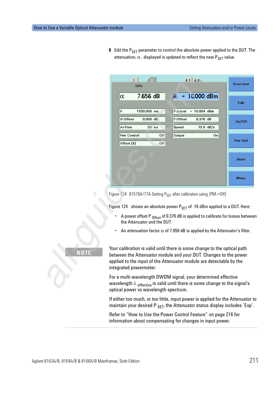
Figure 124 81576A/77A Setting P
SET
after calibration using [PM->Off]
Figure 124 shows an absolute power P
SET
of -10 dBm applied to a DUT. Here:
• A power offset P
Offset
of 0.376 dB is applied to calibrate for losses between
the Attenuator and the DUT.
• An attenuation factor α of 7.656 dB is applied by the Attenuator’s filter.
Your calibration is valid until there is some change to the optical path
between the Attenuator module and your DUT. Changes to the power
applied to the input of the Attenuator module are detectable by the
integrated powermeter.
For a multi-wavelength DWDM signal, your determined effective
wavelength λ
effective
is valid until there is some change to the signal’s
optical power vs wavelength spectrum.
If either too much, or too little, input power is applied for the Attenuator to
maintain your desired P
SET
, the Attenuator status display includes ‘Exp’.
Refer to “How to Use the Power Control Feature” on page 216 for
information about compensating for changes in input power.
NOTE
 Loading...


