Return Loss Measurement Return Loss Measurement
184 Agilent 8163A/B, 8164A/B & 8166A/B Mainframes, Sixth Edition
3 Move to [Terminated calibration] and press Enter. The instrument measures the
power reflected by the component, and sets the [Para] values used by the
Return Loss monitor’s power sensor and monitor diode.
How to Measure Return Loss
It is not necessary to make new calibration measurements for each DUT.
You can make the calibration measurements for your system, and then
measure the return loss of many devices.
The value shown in the result field for the Return Loss channel is the
measured return loss.
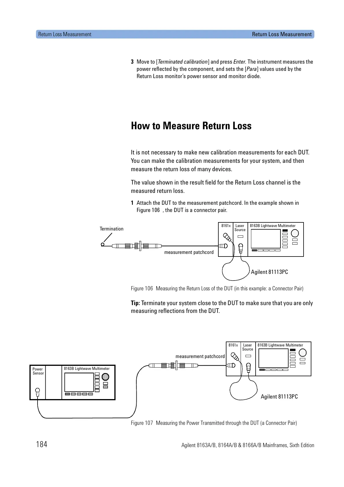
1 Attach the DUT to the measurement patchcord. In the example shown in
Figure 106 , the DUT is a connector pair.
Figure 106 Measuring the Return Loss of the DUT (in this example: a Connector Pair)
Tip: Terminate your system close to the DUT to make sure that you are only
measuring reflections from the DUT.
Figure 107 Measuring the Power Transmitted through the DUT (a Connector Pair)
Termination
measurement patchcord
8161x 8163B Lightwave MultimeterLaser
Source
Agilent 81113PC
Power
Sensor
8163B Lightwave Multimeter
measurement patchcord
8161x 8163B Lightwave MultimeterLaser
Source
Agilent 81113PC
 Loading...


