Return Loss Measurement A Background to Return Loss Measurement
192 Agilent 8163A/B, 8164A/B & 8166A/B Mainframes, Sixth Edition
Measuring the Power Transmitted Through
the DUT
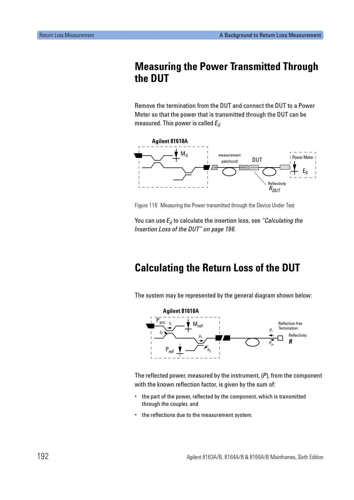
Remove the termination from the DUT and connect the DUT to a Power
Meter so that the power that is transmitted through the DUT can be
measured. This power is called E
il
Figure 116 Measuring the Power transmitted through the Device Under Test
You can use E
il
to calculate the insertion loss, see “Calculating the
Insertion Loss of the DUT” on page 196.
Calculating the Return Loss of the DUT
The system may be represented by the general diagram shown below:
The reflected power, measured by the instrument, (P), from the component
with the known reflection factor, is given by the sum of:
• the part of the power, reflected by the component, which is transmitted
through the coupler, and
• the reflections due to the measurement system.
M
il
measurement
patchcord
DUT
Power Meter
E
il
Agilent 81610A
Reflectivity
R
DUT
Reflection-free
Termination
R
M
ref
P
ref
Agilent 81610A
Reflectivity
P
in
P
r
P
src
t
1
k
1
k
2
t
2
 Loading...


